
Ti-VCT cam timing on a Coyote with HP Tuners
Published
Coyote Ti-VCT changes intake and exhaust valve timing independently on each bank. Tune the requested schedule only after confirming its angle reference, the active control path and actual cam tracking. A mapped-point weight does not, by itself, identify the schedule commanding the cams.
- Intake and exhaust cam timing move independently on each bank. Confirm the angle reference and units before comparing a target.
- Log desired and actual position for every cam. A mapped-point weight does not identify the schedule that is commanding the cams.
- Preserve mechanical limits and diagnostics. A software target cannot establish valve clearance, and a constant target does not lock a phaser.
- Stop if actual cam position does not track the request or a mechanical limit is unknown. Check the phaser and oil system before editing targets.
Read the cam reference and units from the actual definition. Compare desired and actual positions for every cam. Preserve mechanical limits and diagnostics. A software target cannot establish valve clearance, and a constant target does not mechanically lock a phaser.
Full Custom: $249 $199 launch special. Most files in 3–5 business days after complete inputs; the outside limit is 7 business days.
Coyote 5.0 only. HP Tuners hardware and credits are not included. How files are handled.
Application and calibration limits
This procedure concerns Coyote Mustang and F-150 calibrations in HP Tuners. It addresses Gen 1, Gen 2 and Gen 3 control principles, with hardware examples labeled below. It does not supply a transferable stock schedule or extend those examples to Gen 4.
Confirm editor support and exposed parameters for the exact controller before planning an edit.
- The Mustang hardware examples concern Gen 1 2011–2014, Gen 2 2015–2017 and Gen 3 2018–2023 applications. A truck's model year does not authorize importing a Mustang's phasers, angle references or model tables. Record the F-150's actual engine hardware, strategy and induction arrangement separately. Cam swaps and replacement engines make identification by registration year especially weak.
- Gen 2 Mustang intake phasers introduced mid-lock operation. Early Gen 3 Mustang hardware retained that intake arrangement and moved exhaust oil control into the cylinder head. These changes matter when interpreting park positions and actuator response. They do not establish a universal advance window or solenoid holding duty. Read the applicable hardware requirements and the strategy's definitions rather than treating every displayed zero as the same valve position.
- For an unmodified cam and phaser combination, first establish that the original request tracks correctly. A cold-air intake or exhaust change alone is not evidence that the cam schedule needs revision. A manifold, cam or blower change creates a reason to reassess filling and control. It still does not identify the angle that should replace a cell.
How the schedule and mapped-point models interact
- Phasing rotates the valve events relative to the crankshaft. It does not change the lobe's duration or lift. Intake closing influences trapped charge; exhaust timing influences residual gas and gas exchange. Their combination changes overlap, but overlap is only part of the result. Equal airflow readings can conceal differences in pumping work, combustion and delivered torque.
- Separate the target-selection task from the model-selection task. A schedule requests intake and exhaust positions for the current operating conditions. Limits and overrides can alter that request before the actuators try to follow it. The engine models then account for cam state when estimating airflow, spark requirements and torque. Changing the target can therefore change model behavior even when no spark cell was edited.
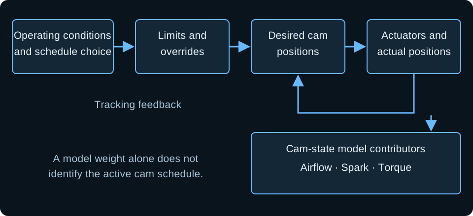
Swipe or use the arrow keys to read every label.
Names such as Optimum Power and Fuel Economy appear in the researched schedule examples. Stability labels also appear, with wording that varies between accounts. Their spelling, enable logic and axes still need confirmation in the open file. Search those terms as leads.
Do not invent a menu path or assume an older Ford variable-cam help page defines the current four-cam strategy.
- A mapped point represents a calibrated cam state used by the models. The models can blend contributions as cam state changes. That is different from deciding which schedule should request the next position. An Optimum Power schedule and a mapped point carrying an OP label need not become active together. Diagnose the request from the schedule evidence and the modeled result from the relevant contributors.
- This distinction explains a common failed edit: enabling a model point and expecting the desired cam trace to move. If the schedule request did not change, larger model edits will not prove that the phasers received a new instruction. Conversely, a schedule change can move the cams while the log still shows contributions from other mapped points. Keep those observations separate before deciding the write failed.
Log the request, response and operating state
Use the Coyote logging guide for recording setup and mixture-channel definitions. For Ti-VCT, build a channel dictionary that identifies the cam, bank, quantity, sign and unit. Desired position, actual position and calculated error must use compatible references. A trace labeled only “cam angle” cannot establish tracking.
| Channel group | Useful evidence | Missing evidence limits the conclusion |
|---|---|---|
| Desired and actual intake, both banks | Request movement, response direction and persistent bank differences | Actual position alone cannot identify the requested schedule. |
| Desired and actual exhaust, both banks | Exhaust response alongside intake during the same event | An intake-only capture cannot establish overlap behavior. |
| Cam error and actuator duty, if exposed | Controller effort and residual error as the target moves | Duty alone cannot prove phaser movement or oil delivery. |
| Schedule state, enables and model contributors | Which request path and model region are active | A model weight alone cannot prove the schedule mode. |
| RPM, elapsed time, pedal, load and throttle | Trigger sequence and time available for cam movement | A plot against rpm alone can conceal transient delay. |
| Oil and coolant conditions | Thermal dependence and measured oil supply where available | An inferred pressure channel is not a measured supply test. |
| Lambda by bank, spark, knock and torque intervention | Combustion and model response after a cam change | Airflow alone cannot establish improved torque. |
A useful baseline includes warm idle, steady light load, a controlled transition, throttle lift and re-entry. Save the codes and freeze-frame evidence before actions that could clear them. Label the fuel, cam hardware, file revision and complaint.
Compare logs made under matching conditions so a temperature change does not masquerade as a successful schedule edit.
- Healthy tracking means the actual traces follow their requests with a response consistent with the operating event and applicable diagnostic criteria. It does not mean every sample is identical. Persistent separation at steady conditions differs from brief lag through a rapid request. Compare banks, target rate and elapsed time before assigning either observation to a failed part.
- If all cams flatten together, determine whether their desired positions also changed. A fault response that parks the cams is different from an actuator failing to follow an unchanged request. Preserve the event leading into the flat region. The decisive evidence may occur during lift, before the next acceleration reveals that cam control has disappeared.
Work through the calibration in order
- Save the as-found read and hardware record. Record controller identity, editor version, cams, phasers, limiters, manifold and IMRC state. Stop if the file's intended hardware cannot be reconciled with the engine.
- Export the relevant schedules and definitions. Include units, axes, enable conditions, limits and mapped-point coordinates. Keep the original descriptions with the exports. Stop if desired and actual angle references remain unresolved.
- Establish the permitted mechanical envelope. For changed cams or phasers, obtain the applicable installation requirements and measured clearance information. Include simultaneous intake and exhaust positions. Stop if the planned combinations have no established clearance.
- Record the baseline through the complaint. Capture all cam requests and responses with operating conditions. Check oil level, specified grade, temperature and measured supply where indicated. Stop calibration work if bank separation, correlation faults or oil-supply evidence points to an unresolved hardware problem.
- Identify the active request path. Compare observed desired angles with interpolated schedule values and applicable limits. Confirm the enable conditions. Stop increasing an edit when the request does not move; find the selector or limiting path first.
- Change a justified region and retain a comparison file. Keep the other cam's request unchanged while establishing cause and effect. Avoid abrupt neighboring transitions. Stop if actual response cannot follow the requested change under the relevant conditions.
- Reconcile the model response. Review airflow, lambda, final spark, knock and torque intervention with the cam-state contributors. Stop if mixture or spark behavior becomes unexplained, even when measured airflow rises.
- Repeat transitions and hot operation. Recheck idle, cruise, lift and re-entry as well as the edited region. A truck also needs its relevant sustained-load conditions evaluated. Restore the baseline if the change creates instability or new faults.
The order prevents a common loop: changing a schedule to cure a tracking fault, then changing the model to conceal the resulting mixture error. Keep a short change record stating which request should move and which logged response would support the change.
If the expected request stays unchanged, the next task is selection diagnosis rather than another angle revision.
- When refining transitions, compare against time as well as rpm. Faster engine acceleration gives the phaser less time to travel through the same rpm interval. A schedule that follows during a slow transition can lag in a lower gear. Moving the target earlier without checking actual response and clearance can create a new problem elsewhere.
- Intake and exhaust effects interact. After establishing a useful intake change, revisit the exhaust comparison within the same verified envelope. Do not assume the exhaust is irrelevant because a single airflow test showed little difference. Conversely, changing both schedules together makes it harder to tell which change affected residual gas, filling or stability.
Check interpolation before calling the request wrong
- A schedule cell describes an axis location, while the log usually passes between breakpoints. Compare the recorded rpm and load with the neighboring cells in the active table. Then account for the applicable limiting path. A desired value between entries can be the expected interpolated result. Changing a distant cell because its number resembles the observed angle will not test the intended region.
- For an arithmetic example, assume a verified table uses linear interpolation along rpm at a fixed load row. Give neighboring cells arbitrary values of 4 and 8 crank degrees at 2,000 and 3,000 rpm. At 2,500 rpm, the interpolated request is 4 + 0.5 × (8 − 4) = 6 crank degrees. If the desired channel reads 6, that agrees before any overrides. These invented values explain the calculation; they are not a Coyote schedule. Between load rows, account for interpolation on that axis too.
- Keep the request calculation separate from any displayed model distance. A distance coordinate can identify blended model contributors without being an angle or a schedule index. Record the definition and display conversion for each quantity. If the exposed channels cannot reproduce the request, state which selector or override remains unknown. Do not force agreement by changing mapped-point coordinates that describe the models.
Recheck the truck's aircharge estimate after phasing changes
- For Gen 2 and Gen 3 F-150 speed-density applications, cam state is part of the context for estimating cylinder filling. Check the active aircharge model with MAP, temperature, lambda and fuel correction through the edited region. A changed cam schedule can expose model error that was less visible at the previous state. Correct injector characterization remains necessary; bending injector data to conceal the error spreads it into other conditions.
- A Mustang MAF comparison cannot settle that truck-model question. Nor does a calculated airflow channel establish that the truck physically measures inlet mass flow. Keep the application and sensor architecture attached to the recording. For a truck used under sustained load, inspect the return to light load after the hot event as well as the loaded region. That transition can select a different schedule and different model contributors.
- Fuel changes also need a separate explanation. E85 does not prescribe a phaser position or increase mechanical clearance. It can change the combustion constraints under which a cam comparison is made. Establish fuel delivery and known fuel composition before interpreting a difference as a cam benefit. Retain the fuel label in every comparison so a change in knock behavior does not get credited solely to valve timing.
Use the symptom to choose the next check
| Observed behavior | Next check | Calibration consequence |
|---|---|---|
| Desired angle ignores the edited schedule | Active path, enables, interpolation, limits and written file identity | Locate the effective request before changing more cells. |
| Desired moves; actual stays displaced | Reference agreement, oil conditions, circuit, phaser and mechanical timing | Do not relax diagnostics to hide the separation. |
| Cams park after lift | Preceding error, fault state, desired change and duty response | Capture the lift event before proposing a rate change. |
| Low-load surge after IMRC removal | Retained economy scheduling, cam state and combustion response | Reconcile the altered combination rather than copying a fixed-angle recipe. |
| Knock appears after distance-table edits | Changed model contributors, borderline, MBT and final spark | Review the newly used model region before treating knock as noise. |
| Hot tracking loss after a cam change | Cam oil-feed compatibility and temperature-dependent oil supply | Establish hydraulic control before refining targets. |
A manifold change with low-load surge
- Owner reports describe surge after IMRC removal while the retained economy behavior still used cam states suited to the original combination. Restricting the states used at light load reportedly smoothed operation, sometimes with reduced part-throttle torque. That is evidence to investigate the changed combination. It is not a stock calibration template or a reason to collapse every cam state.
- Work the event from pedal and load to desired cams, actual cams and model contributors. Check mixture and final spark when the surge starts. If altered cam selection cures the symptom, compare the newly used airflow and spark models before accepting it. A smoother engine can still have an incorrect torque estimate or unnecessary fuel correction.
- The repair clue is the loss of charge motion as well as the cam state. The original runner controls supported mixing at low speed. Before revising the light-load schedule, check the installed manifold, remaining actuators and position feedback against the file. A mechanically stuck runner system and a deliberate removal require different repairs. After a calibration change, repeat the same warm, steady-pedal event and its transition back to idle.
A cam change with loss of control after lift
- A reported Gen 3 2022 Mustang running E85 with aftermarket cams lost desired-versus-actual agreement after throttle closure and then parked the cams. The owner had replaced intake solenoids but did not consider them the cause. The account does not establish a completed repair or prove a tune-side cause. Its useful finding is the location of the event: capture deceleration and the preceding request change, rather than stopping the log at lift.
- Separate Gen 3 Mustang cam-change reports described leakage around the aftermarket cam nose as oil warmed. Control returned after stock cams were reinstalled. That supports checking hardware compatibility, but does not establish the cause of the separate 2022 case.
- Compare the replacement cam's oil passages and sealing surfaces with the required hardware before altering control rates. Gen 3 exhaust cam journals also have specific oil seals; inspect their installation separately from an intake-side complaint.
A worked reading of a failed schedule edit
- Consider a hypothetical Gen 2 Mustang whose owner changes the Optimum Power intake schedule but sees no difference. The new recording shows the same desired intake trace as the baseline. Actual intake follows that unchanged request. A mapped-point display still shows contributions from other points. These observations do not establish a sluggish phaser; the requested position never changed.
- First compare the written revision and exact edited region with the operating conditions. Then check the active schedule, its pedal and load conditions where applicable, and any clamping path. If that strategy exposes no schedule-state channel, document the request comparison as indirect evidence. Do not call a model weight a substitute for the missing selector signal.
- Suppose the corrected selection now changes desired angle and actual follows it. The next check is the combustion and model response, including the transition back to cruise. This closes a request-selection diagnosis. It does not prove that the new angle improves torque. The example describes a diagnostic method, not a recorded customer repair or a target map.
A confirmed crank-degree and cam-degree comparison
For the Gen 1 2011–2014 Mustang application, the COMP 5493CPG limiter listing specifies travel of 20 crank degrees, equivalent to 10 cam degrees. The cam rotates at half crankshaft speed. This is a component's restricted travel, not a factory schedule, an advance target or approval for every simultaneous cam combination.
- The Gen 2 2015–2017 Mustang COMP 243430 cam example instead works with the specified mid-lock arrangement without additional phaser limiters. That requirement belongs to that product and application. It does not establish clearance for a different grind or authorize using a Gen 1 limiter configuration on a Gen 2 engine.
- Write the angle unit and zero reference beside every exported schedule and Scanner channel. A crank-versus-cam conversion changes scale; a different park reference changes the offset. Neither problem is solved by reversing the sign alone. Read the allowable request and limit values from the matching file and hardware instructions before comparing another vehicle's curve.
Questions about Coyote Ti-VCT
Am I using the mapped points for the cams, or the Optimum Power tables
Separate cam scheduling from model weighting. The repeated real-world confusion comes from an OP model point appearing disabled while an Optimum Power cam schedule remains usable. Check the schedule's actual enable logic and the logged desired position. Then inspect which cam-state models contribute to airflow, spark and torque.
The shared label does not make them the same operation. Both pedal and load conditions appear in the researched schedule examples, but their exact logic must be confirmed in your strategy. A missing OP weight alone does not establish that the requested cam schedule is inactive.
What do the IVO and EVC numbers mean, and are positive numbers retard
IVO names intake valve opening and EVC names exhaust valve closing, but a software field may express an event, phaser offset or model coordinate. Read its definition before interpreting its sign. The negative-intake-as-advance convention in the Gen 2 Mustang experiment belongs to that command frame.
It does not settle every channel in a Gen 1 Mustang or an F-150. Do not add a copied base-event constant to an angle without establishing what each quantity represents. Overlap calculations also require compatible event references and the same lift definition, not merely the sum of two displayed phaser commands.
If I change the economy distance tables, do I have to change spark
You must recheck the spark model regions that the engine now uses. Reported economy-distance edits changed the contributing mapped points and were followed by knock. That does not prescribe a timing correction; it identifies what to inspect.
Compare cam state, point contributors, corrected borderline and MBT behavior with final spark and knock response. Check mixture at the same time. A previously unused region can carry unsuitable values for the changed hardware. Restore the prior change if the new combustion behavior remains unexplained.
Do not reduce knock sensitivity to make the comparison appear clean.
For a simplified weighting example, suppose confirmed contributors are 25% from model A and 75% from model B. If the relevant spark values are 20 and 24 degrees, their linear blend is 0.25 × 20 + 0.75 × 24 = 23 degrees.
This is only a model-term calculation; corrections and spark selection can change final timing. Use actual logged weights, not an assumed percentage derived from a distance label.
Can a bad VCT solenoid cause a misfire
A cam-control problem can disturb cylinder filling and combustion, but a misfire does not identify the solenoid as its cause. Compare the affected bank's request and actual position, fault evidence and actuator response. Also check oil supply and mechanical timing through the appropriate diagnostic procedure.
Harvested repair accounts include a damaged solenoid followed by cleared cam faults, and a restricted screen in another case. Those outcomes identify possible causes rather than a parts-replacement order. A cam-control fault that persists after a solenoid replacement needs further diagnosis, not a more aggressive angle request.
Does this cam error mean the bank is off a tooth, or is the Scanner PID wrong
Establish units, zero references and channel identities first. Compare the same cam type on both banks through startup and warm operation. A persistent offset can justify a mechanical-timing investigation, but a mismatched PID reference can imitate one. Correlation, target-tracking and circuit monitors evaluate different evidence.
An instantaneous angle difference is not a universal Ford fault threshold, and elapsed time and enabling conditions matter. Preserve the exact codes and strategy-specific diagnostic information. Do not change the monitor thresholds merely because a display is inconvenient or another car shows a similar separation.
Is a flat exhaust schedule from a blower file a starting point
It is a comparison lead, not a transferable target. A flat exhaust request in a particular blower calibration reflects that engine's manifold, pressure relationships, cams and control strategy. A naturally aspirated, centrifugal-blower or turbo combination can behave differently. Check actual tracking and gas-exchange effects alongside torque and combustion.
The Gen 2 2017 Mustang truck-manifold experiment used 93-octane E10 and found little exhaust-related airflow change. That does not establish exhaust timing as irrelevant. Retain the original schedule until the intended change has a hardware-specific reason and evidence from the vehicle being calibrated.
What are phase limiters doing besides making timing more consistent
A limiter restricts physical phaser travel; a lock fixes a physical position. The calibration must match whichever device is installed. Neither is equivalent to typing a constant schedule into software. With aftermarket cams, usable travel concerns valve clearance and actuator compatibility as well as repeatability.
Stock overlap borders describe the original geometry and cannot establish clearance after a cam change. Obtain the measured envelope and product-specific requirements before commanding new combinations. Lockout torque-loss claims from a different engine are also unsuitable as a fixed prediction for a Coyote Mustang or F-150.
Why do my cams keep going back to zero at idle
Determine whether desired positions return there or actual positions depart from their requests. Idle control, startup conditions, limits and fault parking can produce different versions of that symptom. Zero itself needs a defined reference. Deliberately increasing idle overlap for a ghost-cam sound changes residual gas, vacuum and combustion stability.
It can also make oxygen feedback misleading when misfire is present. Do not disable stability or emissions scheduling as a generic cure for a returning idle target. Diagnose the active path and preserve a functioning idle baseline before considering any change to the requested state.
Is there a reason not to run one mapped point from idle through cruise
The IMRC-removal reports show why someone tried it: reducing the light-load cam states stopped the surge. One smooth combination also lost part-throttle torque. Keeping one model point active across changing cam positions can leave its airflow, spark and torque tables describing the wrong state.
If you simplify the cam request too, recheck those models through the whole region. Treat the reported cure as evidence about that combination, rather than deleting the same point numbers from every file.
What does Ti-VCT give us in cylinder pressure that ignition timing does not
Valve timing changes how much fresh charge remains in the cylinder and how much exhaust gas stays with it. Moving intake closing changes when compression of the trapped charge begins. Spark timing changes when that charge burns.
Advancing spark cannot replace charge lost through an unsuitable intake-closing event, and phasing cannot correct an unsuitable spark map. After the cams track a revised request, recheck mixture, spark and torque behavior together.
Would more boost change the VCT target
A pressure change gives you a reason to reassess the schedule, but it supplies no angle correction by itself. The pressure difference across the valves during overlap affects whether charge stays in the cylinder, reverses or escapes into the exhaust.
A positive-displacement blower, centrifugal blower and turbo system can have different pressure relationships at the same inlet boost reading. Compare the actual combination and cam response before copying a flat exhaust schedule from another blower file.
Tune Report is free for a readable file and matching log; include the cam hardware and the event where tracking changes.
Full Custom is open on Ford and starts with confirming the supported application and required cam, fuel and log evidence. There are no stage tiers.
Tune Report is free if you want this file checked: open the Ford Tune Report.
A written review of your tune file and one log from your car.
Start a Ford Tune Report