
6R80 shift tuning on a Coyote with HP Tuners
Published
Tune a Coyote 6R80 by identifying the active shift schedule, measuring when the command starts and checking how the transmission completes it. A flare does not identify an offgoing-pressure correction. Engine rpm alone cannot separate clutch slip from converter slip, and a pressure increase cannot repair an unreliable speed signal.
- Identify the active shift schedule before changing a shift. The same pedal and gear can select a different schedule.
- Measure when the command starts and how the transmission completes it. Engine rpm alone cannot separate clutch slip from converter slip.
- Use turbine, output and engine speed with the engaged ratio. A pressure increase cannot repair an unreliable speed signal.
- Stop if the speed ratio or signal is inconsistent. Diagnose the circuit or mechanical fault before adding pressure.
Full Custom: $249 $199 launch special. Most files in 3–5 business days after complete inputs; the outside limit is 7 business days.
Coyote 5.0 only. HP Tuners hardware and credits are not included. How files are handled.
Identify the vehicle, strategy and transmission
This procedure covers original Coyote 5.0 applications with the 6R80. These are Gen 1 2011–2014 Mustang and F-150, and Gen 2 2015–2017 Mustang and F-150. Confirm transmission identity from the vehicle and read. A swapped engine's generation does not identify the transmission controller, solenoid calibration or available tables.
- Use HP Tuners VCM Editor for the calibration and VCM Scanner for the matching recording. Save the as-found read, strategy and operating-system identifiers, software build and available controller information. Confirm licensing and write support for that exact application through Ford getting started. Do not infer a separate controller or credit charge from another Ford transmission.
- Record converter identity, transmission changes, valve-body or solenoid work, axle ratio and actual tire circumference. Solenoid identification and programmed characterization must agree with installed hardware. Keep the engine torque-model changes in the record too. This page addresses calibration and diagnosis; an unresolved hydraulic or speed-sensor fault stops the tuning procedure.
No verified stock-versus-modified pressure, fill-time or shift-rpm range is established across these applications. Read each value, axis, unit and description from your file. A Mustang recipe does not establish an F-150 towing calibration.
Separate the schedule from the completed shift
The schedule requests another gear. Clutch control transfers torque between elements while engine control coordinates input torque. The converter has its own apply, release and controlled-slip behavior. A change in engine speed can therefore describe several different events. Identify which event moved before deciding which table was responsible.
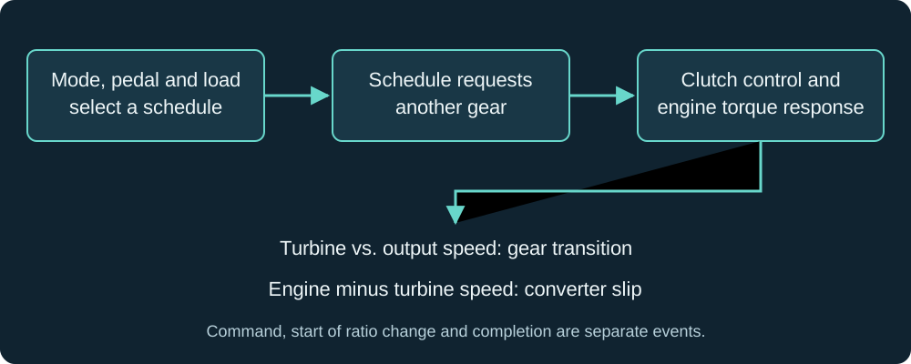
Swipe or use the arrow keys to read every label.
Mark the command change, the beginning of turbine-speed movement and the established destination ratio separately. A current-gear channel can be calculated or delayed; it is not an independent measurement of clutch engagement. Confirm completion against turbine and output-shaft speed where those signals are available and valid.
- With a gear fully applied, turbine rpm equals output-shaft rpm multiplied by the engaged ratio. Engine rpm differs from turbine rpm by converter slip. During the shift, the transmission is transferring between ratios, so the steady-gear identity cannot describe every sample as a completed gear.
- Keep two differences separate in the review. Engine minus turbine speed describes converter behavior. Turbine speed versus expected engaged-gear speed describes internal ratio behavior. A converter release can raise engine rpm while turbine speed follows the intended gear transition. That observation does not establish an internal clutch flare.
- The engine's torque estimate is also part of the control model. An airflow or torque-model edit can change transmission behavior without a transmission-table edit. If estimated torque understates the input, pressure or capacity calculations can work from the wrong load. Raising a pressure ceiling leaves that input error unresolved.
Record the command and the response together
Use the Coyote logging procedure to establish channel availability and recording quality. The names below describe required quantities, not a fixed list of Scanner PID labels. Save the exact channel definitions and units. An unsupported signal should remain a stated gap rather than being replaced by an unrelated display.
| Quantity | What it establishes | What it cannot establish alone |
|---|---|---|
| Pedal, throttle and selected mode | Driver request and the conditions selecting a schedule | The active table merely from a dashboard mode label |
| Requested and current gear | Command timing and reported gear state | Physical clutch completion without speed evidence |
| Engine, turbine and output-shaft rpm | Converter difference and internal ratio trajectory | A failed clutch element from an engine-speed spike |
| Vehicle speed, transmission temperature | Schedule position and thermal comparison | Identical conditions merely because the engine is warm |
| Estimated torque, torque request and intervention source | Load input and shift torque coordination, where exposed | Measured engine torque from a calculated channel |
| TCC request, state and target/actual slip | Apply, release or controlled-slip context | Full lock from a generic engaged flag |
| Available pressure/capacity requests and adapt values | Controller intent and learned correction | Physical line pressure without a measurement |
Record the approach, shift and settled operation afterward. Keep the same mode, load region and transmission temperature when comparing revisions. A warm loaded shift and a cold light-throttle shift do not test the same calibration region. Keep cold behavior as a separate comparison, with its own baseline.
- A useful trace shows valid speeds, an understandable command and a repeatable transition toward the new ratio. A suspect trace shows sensor dropout, unexplained turbine acceleration, prolonged ratio departure or a result that changes as learning accumulates. None needs a universal acceptable-slip number to justify further diagnosis.
- If turbine speed is unavailable, state the limitation before interpreting engine rpm. Converter release and internal flare may remain inseparable. Adding unrelated channels will not recover the missing measurement, and a busy recording can make event order harder to resolve. Keep the event channels sampled well enough to distinguish their timing.
Work through an apparent flare in the log
- Consider invented samples from a settled fourth gear using the 2015 Mustang ratios below. At 2,000 rpm output speed, expected turbine speed is
2000 × 1.14 = 2280 rpm. If measured turbine speed is 2,280 rpm and engine speed is 2,580 rpm, the converter difference is2580 − 2280 = 300 rpm. That sample agrees with fourth gear internally, although it does not establish whether the converter slip is intended. - If turbine speed instead remains at 2,480 rpm after the shift should have settled, the internal difference is
2480 − 2280 = 200 rpm. Check the speed signals, command and transition before assigning a clutch fault. During the transition itself, departure from the destination ratio is expected. These invented differences are arithmetic examples, not allowable-slip limits.
Work through the calibration in order
- Preserve the as-found condition. Save the read, DTCs, freeze-frame information and available learning data. Stop before resetting anything if the complaint includes missing speed, an unexpected downshift or ratio faults.
- Establish control and hardware health. Verify fluid specification and level through the applicable temperature procedure. Check sensor plausibility, converter identity and solenoid characterization. Stop calibration work when an unresolved fault prevents a repeatable baseline.
- Inventory the applicable schedules. Record normal, sport, tow/haul, coastdown and manual paths where present. Export values with their units, axes and conditions. Stop if the intended schedule or cell unit cannot be identified.
- Read the relevant limits. Compare engine protection, transmission constraints and the hardware's permitted speed. Inspect knock-control coverage in the actual strategy. Stop when the planned event exceeds an established boundary or requires an unknown protection change.
- Capture the unchanged event. Mark requested gear, turbine movement, destination ratio and converter state. Stop if dropout or inconsistent operating conditions make the comparison ambiguous.
- Change the justified schedule region. Preserve neighboring transitions and a clear revision record. Use the supported write operation for the identified controller. Stop increasing the edit if the command does not respond; find the active selection or constraint.
- Evaluate completion separately. Compare the new command with turbine trajectory, torque coordination and converter behavior. Stop if a moved command exposes flare, bind, shudder or unexplained limiter intervention.
- Recheck learning and other conditions. Repeat the affected modes, thermal regions and load transitions. Accept the change only when the improvement persists and the surrounding behavior remains understood.
Choose the schedule before changing the threshold
- Read whether the value represents engine rpm, output-shaft speed or road speed. Then read what selects that schedule. The axis can be pedal, torque, speed or another operating quantity; the axis unit does not automatically describe the cell. Preserve the definition alongside the export so another revision cannot silently change the interpretation.
- Legacy Ford help includes labels such as
Trans WOT Shift RPM 1->2andTrans Upshift Speed 1->2 vs. TPS. Those labels explain broad categories, but they do not establish every current 6R80 parameter. Confirm the exact definition rather than assigning an old help page's units to a differently named table. - If an rpm edit leaves the command unchanged, compare competing schedules, mode selection, limits and any prediction or anticipation logic. Do not assume every operating system chooses the lower of rpm and road-speed thresholds. Raising other thresholds beyond use merely to remove them conceals which path was controlling the event.
Measure latency rather than deriving a target from fill time
- A fill-time entry describes a control quantity, not a complete stopwatch for the event. Preparation can precede a visible ratio change, and prediction can alter when a request appears. Measure the sequence in your recording. A copied fill value cannot establish the command needed for a desired completed-shift rpm.
- For an analytical example, assume engine acceleration is 1,500 rpm per second and an event takes another 0.20 seconds. The engine can gain 300 rpm during that interval. These are invented inputs for arithmetic, applicable to no particular vehicle. They explain timing sensitivity without prescribing a margin or a shift point.
- Use the actual local acceleration rate and timestamps when reviewing a vehicle. Converter changes can alter engine acceleration during the same interval, so extrapolation remains a check rather than a controller model. A limiter source at the event requires diagnosis of the command and protection path. It does not justify raising every limit.
Interpret firmness tables by quantity and phase
- Oncoming refers to the element accepting torque; offgoing refers to the element releasing it. Pressure, current, capacity, multiplier and duration are different quantities. Their edit directions cannot be inferred from a shared pressure-related label. Establish the table description and solenoid behavior before deciding whether an increase provides more holding force.
- Fill prepares an applying clutch. Torque transfer and inertia change then have to remain coordinated with release and engine torque. Shortening every duration can leave insufficient preparation. Holding a releasing element too long can cause overlap or bind. A sharper sensation does not establish a cleaner torque handoff.
- Keep shift torque coordination active while establishing the baseline. A throttle movement or spark reduction can be an intended shift response. Diagnose the intervention's source and timing before treating it as unwanted restriction. An engine tune that misreports torque can produce a different shift even when every transmission table remains untouched.
Check converter transitions and truck load
- Read the converter apply and release conditions together. A change that makes apply and release alternate near a cruise operating point can create repeated cycling. Compare the state changes with pedal, gear and temperature before treating the resulting engine-speed movement as gear hunting. A desired-slip entry also needs its own definition; it is not automatically an apply-speed threshold.
- After changing a shift schedule, review whether converter apply now overlaps a different part of the shift. Inspect the settled state as well as the transition. A brief difference during an apply event and sustained slip during commanded full lock are different observations. Neither supports forcing every slip-related value to zero.
- For the scoped F-150 applications, preserve the intended tow/haul behavior and compare loaded operation separately from unloaded driving. Include grades, sustained load and the return to cruise. Earlier lockup can reduce converter slip while increasing engine load or lugging. Follow the installed converter's requirements and vehicle-specific temperature guidance rather than assigning a universal towing cutoff.
Preserve speed-fault evidence before a reset
- An implausible output-speed signal changes the foundation of schedule diagnosis. Program 16N02 identifies certain Gen 1 2011–2012 F-150 and 2012 Mustang vehicles with intermittent leadframe-related OSS faults. Applicability is VIN and build dependent. This historical program does not establish current coverage or diagnose every vehicle with an odd shift.
- Save the exact codes and the signal leading into the event. Verify the applicable diagnostic path before changing the schedule or suppressing a monitor. A controller reacting to a missing input is different from a healthy controller choosing an unwanted shift. Repair evidence must establish a valid input before schedule tuning resumes.
Use the symptom to choose the next check
| Observed event | Next comparison | Decision |
|---|---|---|
| Command stays unchanged after a schedule edit | Written revision, mode, interpolation and constraints | Locate the effective schedule before changing magnitude. |
| Engine rises while turbine follows the new ratio | TCC release, apply timing and converter slip | Do not diagnose internal flare from engine rpm alone. |
| Turbine departs from the expected transition | Apply/release timing, torque intervention and hardware health | Establish the phase before selecting an element table. |
| Cold harshness follows a broad table scale | Original thermal rows and shared-element coverage | Review the affected region without imposing a new universal percentage. |
| Improvement disappears as learning returns | Adapt direction, solenoid characterization and hydraulic checks | Investigate recurrence rather than resetting repeatedly. |
| Output speed drops out or becomes implausible | Saved fault evidence and applicable sensor diagnosis | Stop schedule edits until the input is valid. |
A recurring light-throttle flare after pressure changes
- A reported Gen 2 Coyote swap retained a light-throttle upshift flare despite valve-body and leadframe replacement, adaptation resets and higher maximum-line settings. An apparent improvement lasted only briefly. The account does not establish a final repair. It demonstrates why a better first drive is weak evidence for accepting a pressure edit.
- Compare the same event before reset, immediately afterward and after learning develops. If the command is stable but the turbine trajectory deteriorates again, investigate phase control and hardware. Correct-looking commands cannot establish the actual hydraulic response.
A 2–3 complaint resolved by solenoid repair
- A documented 6R80 repair case alternated between a 2–3 flare and a brief bind after an adaptation drive. The 1–2 also varied between slow engagement and a bump. Electrical command patterns stayed consistent. Replacing the C/2–6 and B/3–5–R solenoids, then resetting adaptations and repeating the learning drive, resolved that case.
- The case does not identify a Coyote year or establish those parts as the repair for a 3–4 flare. It shows why the same solenoid's apply behavior on one shift and release behavior on another belong in the diagnosis. Check the installed solenoid band and programmed characterization, and use the applicable service learning procedure. Tight clutch clearances also need investigation when a rebuilt unit binds.
A softer daily shift after a tune revision
- Gen 2 Mustang owners reported harsh part-throttle shifts becoming more comfortable after softer transmission revisions. One owner needed two revisions and reported gentler daily shifts while higher-load shifts remained firmer. Another requested a change to the 1–2 and felt softer shifts throughout the transmission. That result supports checking shared elements and table coverage. It does not establish a pressure percentage that transfers between files, tools or converters.
- Define the complaint by load and temperature before asking for a softer file. Compare the changed tables with the logged region and test adjacent shifts that share the edited control. If cold operation is the only complaint, a broad warm-region reduction creates another variable without testing the original explanation.
Use confirmed ratios for the speed calculation
The following hardware ratios are scoped to the Gen 2 2015 Mustang automatic. They are not recommended shift points or a universal truck calibration. Validate the ratios for another vehicle or swapped transmission. Correct tire and axle representation through the supported method; do not falsify internal ratios to move a schedule.
| Gear | Turbine rpm / output-shaft rpm |
|---|---|
| First | 4.17 |
| Second | 2.34 |
| Third | 1.52 |
| Fourth | 1.14 |
| Fifth | 0.87 |
| Sixth | 0.69 |
For a calculation using that Gen 2 2015 Mustang ratio set, assume a turbine speed of 7,500 rpm in first. Output-shaft speed is 7500 / 4.17 = 1798.6 rpm. At unchanged output speed after the first-to-second transition, turbine speed is (7500 / 4.17) × 2.34 = 4208.6 rpm. Rounded results use the unrounded intermediate calculation.
- The assumed turbine speed is arithmetic input, not a stock point, tuned target or hardware approval. Engine rpm equals those turbine values only when converter slip is negligible. With appreciable slip, use the measured turbine signal. On a downshift, calculate the expected turbine speed using the destination ratio before considering converter effects.
- Axle ratio and rolling circumference convert output-shaft speed into road speed; they do not change the internal gear ratio. A tire correction and a shift-schedule correction solve different problems. Confirm the speed representation first so a schedule edit does not compensate for wrong vehicle geometry.
Questions about 6R80 shift behavior
Why does it flare on the 3–4?
First establish whether engine speed alone rises or turbine speed also departs from the intended transition. A converter event can imitate clutch flare in an engine-only trace. Then compare command timing, torque coordination and the apply/release sequence.
Reported cases include boost changes and a light-throttle complaint that survived higher line settings; neither establishes one failed element. More offgoing holding force can change overlap and can produce bind. Preserve the baseline and investigate hydraulic or solenoid behavior when the response remains wrong despite plausible commands.
The symptom names the event to measure, not the table to increase.
The 1–2 is violent when cold, and it short-shifts. Can both be fixed?
Treat firmness and shift scheduling as separate observations. Record the actual transmission temperature, selected mode, pedal and command timing. Compare the cold table region with the original read, including any broad scaling and shared-element effects. Owner reports describe harshness easing with temperature and softer revisions improving daily shifts.
Those observations justify a temperature comparison, not a conclusion that cold fluid is the sole cause. If the command occurs early, diagnose its active schedule separately from the clutch response. Persistent harshness with an unchanged calibration still needs fluid, solenoid and hydraulic diagnosis before another edit.
What do oncoming pressure, offgoing pressure, boost time and clutch fill time actually do?
They describe different parts of clutch preparation and torque transfer. Oncoming and offgoing identify applying and releasing elements; fill concerns preparing a clutch to accept load. A boost-related table may change support during a phase, but its element, temperature coverage and units must come from the actual definition.
Do not treat every displayed value as measured pressure. A current table can have a different response direction, and a capacity table represents a different quantity. Export descriptions and axes before editing. Shared-element control also means a change intended for one shift can affect another transition that uses the same element.
If torque management is off, will a stock or shorter clutch fill time burn the clutches?
A fill-time number alone cannot answer that. Clutch preparation, input torque, release timing and available capacity act together. Retain torque coordination while establishing a healthy baseline instead of using extra pressure to compensate for its removal.
Reported failures associate poorly controlled shifts with inappropriate torque-management changes, but they do not establish a universal minimum fill time. An aftermarket clutch pack also does not dictate that fill must always increase. Its clearance and hydraulic requirements need the builder's application-specific information.
Verify the turbine trajectory and repeat behavior; a quick or hard shift is insufficient evidence that the handoff is correct.
Is it slipping or just a slow shift?
A slow transition includes slip while ratios change; the useful question is whether its trajectory matches the intended control and hardware. Overlay engine, turbine and output speeds with requested gear and TCC state. Under commanded full lock, engine and turbine speed should converge, but controlled-slip operation intentionally permits a difference.
A generic lock flag cannot establish that target. Do not request hard lock everywhere or assign a universal acceptable slip threshold. After moving shift points, recheck converter transitions and apply/release separation. For an F-150, include its actual loaded and tow/haul use instead of copying an unloaded Mustang schedule.
Why does a tune change help for a few miles, then the flare returns?
A changed learning state can temporarily change the symptom. Compare available adapt data and the same operating event before attributing improvement to edited cells. A battery disconnect, calibration write and supported adaptation reset are not interchangeable operations.
Use the actual service procedure for the identified strategy after a relevant repair or major change. No universal mileage or Sport-mode learning sequence is established here. Repeated resets that recreate a short improvement do not close the diagnosis.
Preserve the recurring event and investigate solenoid characterization, hydraulic response and the torque input before accepting another pressure revision.
How are the slip, fill, torque-transfer and line-pressure tables oriented if the axes are not labeled?
Do not infer orientation from another generation's screenshot or an isolated cell value. Save the controller identity, software build, parameter description and displayed units. Check the current definition and obtain the missing axis information before editing. Temperature, torque, element and gear are different ways of indexing control.
A desired time is not a pressure request, and a reported request is not physical line pressure. The older Explorer and non-Coyote truck examples in circulation cannot establish Coyote table semantics. Missing labels are a definition problem to resolve, rather than permission to test a copied percentage.
Why is it in fifth at 35 mph and sixth by 40?
Those are an owner's reported shift speeds, not factory thresholds. Check the mode, pedal region and speed units in the active part-throttle upshift schedule. Compare the matching downshift schedule too. If a small pedal change immediately requests the previous gear, moving only the upshift can leave the cycling complaint unresolved.
Confirm axle and tire representation first. Then compare command timing before and after a local edit, keeping firmness changes separate.
Why does my 2017 GT upshift by itself in paddle mode?
The 2017 Mustang owner's manual includes a full-pedal exception to its statement that SelectShift holds gear near the rpm limit. It also distinguishes temporary paddle selection in Drive from manual control in Sport. Record selector position, pedal, paddle request and commanded gear before assuming the transmission ignored a command.
The reported tuned-car complaint does not establish which condition caused its extra upshift. Compare the original and modified manual-mode behavior in that exact strategy before changing protection or schedule settings.
What is the maximum line pressure, and will raising it fix the flare?
A maximum-line entry is a ceiling on a control request, not proof of delivered pressure. Raising it may leave the affected event unchanged when another request, phase control or hydraulic condition determines the result. The recurring light-throttle case above did not improve durably after higher maximum-line settings.
Establish the active request and use a physical pressure test when the service diagnosis calls for one. A pump-pressure limit cannot be established from a Scanner channel without confirming what that channel represents.
Does adding a blower change the stall speed of the same converter?
It can. Coyote owners describe higher observed stall after adding a blower, including one who had the converter restalled afterward. Stall behavior depends on the engine's torque curve and the converter combination. A catalog stall number alone cannot predict the result after a torque increase.
Give the converter builder the current and planned engine combination, vehicle weight, gearing and use. Keep launch stall, converter slip during a shift and settled clutch lockup separate in the log; they describe different operating conditions.
Tune Report is free for a readable file and matching log; include transmission identity, converter details and the recurring shift event.
Full Custom is open on Ford and starts with confirming application support and the required file and log evidence. There are no stage tiers.
Tune Report is free if you want this file checked: open the Ford Tune Report.
A written review of your tune file and one log from your car.
Start a Ford Tune Report