
Coyote cam tune: Mustang GT cams, superchargers and E85
Published
A Coyote cam tune starts with the installed valve events. Cams change the models tied to them, a supercharger changes airflow, charge temperature and fuel demand, and E85 changes the fuel calculation and permitted spark. In HP Tuners, each change needs a file that describes the installed combination and a log that tests its assumptions. Adding fuel or raising torque limits alone does not establish that match.
- Each hardware change needs a file that describes the installed combination and a log that tests its assumptions.
- Aftermarket cams need the installed valve events and the models tied to them. A cam label alone is not a calibration.
- A supercharger changes airflow, charge temperature and fuel demand. Adding boost or raising a torque limit does not establish that match.
- E85 needs the measured blend and enough fuel-system capacity. Stop if injector, pump or fuel-composition data is unknown.
Full Custom: $249 $199 launch special. Most files in 3–5 business days after complete inputs; the outside limit is 7 business days.
Coyote 5.0 only. HP Tuners hardware and credits are not included. How files are handled.
Identify the Mustang GT or F-150 5.0 before comparing files
- This procedure covers calibration requirements for Gen 1–3 Mustang and F-150 Coyote combinations. Revised 2021-and-later F-150 hardware and controller support require separate identification. It does not extend a Gen 3 Mustang file to a later truck or a Gen 4 Mustang. Record the engine, controller strategy, software build, transmission, fuel and installed components before making a comparison.
- Keep the original read and the as-found log. A previously modified file is evidence of what was delivered, not evidence of the correct injector or cam data. Establish which engine parts remain original. A vehicle year cannot identify replacement heads, cams, phasers, fuel pumps or an altered intake arrangement.
| Application | Starting distinction | What the file must establish |
|---|---|---|
| Gen 1 Mustang and F-150 | Port injection; identify the actual air-meter arrangement and phaser hardware | PI data, pressure assumptions, supported cam control and installed intake |
| Gen 2 Mustang | Port injection and Mustang MAF calibration | Meter characterization, mid-lock phaser compatibility and fuel reserve |
| Gen 2 F-150 | Speed-density/MAP air model; some factory flex-fuel applications | Cam-state filling model, fuel certification and actual modified-system capacity |
| Gen 3 Mustang and F-150 | Port plus direct injection; Mustang and truck air models differ | Both fuel circuits, injection allocation, DI window and pump-drive compatibility |
| Revised 2021+ F-150 | Identify the revised truck engine and exact controller separately | Current support, exposed definitions and hardware-specific evidence |
- The Gen 3 2018 Mustang gasoline application excludes E85 and fuel above 15% ethanol in its original specification. The Gen 2 2016 F-150 5.0 has a factory flex-fuel specification. Those are different starting points. Verify the exact vehicle's certification and any changes made by a blower package. Factory ethanol compatibility does not establish enough fuel delivery for additional airflow.
- Use the current VCM Editor definition to inventory parameters, axes, units and help text. The areas named below describe control functions; they are not a promise of identical menus across strategies. When a definition does not expose a required function, obtain support or a matched calibration dataset before proceeding. A similarly named legacy Ford parameter is insufficient evidence.
How the modifications change the control model
The PCM needs a consistent account of air, fuel and torque. Cam position affects cylinder filling and residual exhaust. A blower changes pressure and temperature as well as air mass. Fuel composition changes the mass needed for the commanded lambda. The resulting torque estimate also affects throttle intervention and automatic-transmission control.
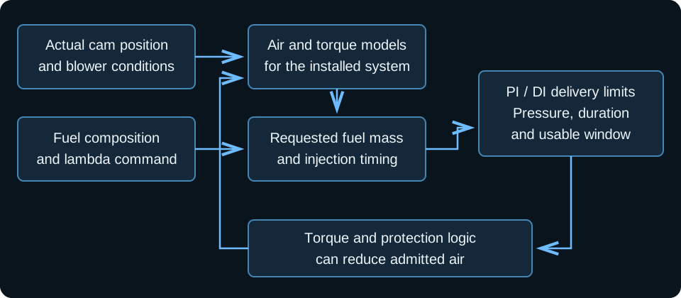
Swipe or use the arrow keys to read every label.
Keep the physical injector description separate from the requested mixture. Changing cams does not change the flow characteristics of an unchanged injector. Changing ethanol content changes the fuel calculation; it does not justify inventing a different injector slope.
A pressure-reference change can require different characterization, but that must describe the actual injector and system.
- On a MAF-equipped Mustang, retain an accurate electrical-signal-to-airflow relationship for the installed meter housing. A cam change also affects cylinder filling and the models associated with actual cam position. On a Gen 2 or Gen 3 F-150, work with the truck's speed-density model. Calculated airmass in Scanner does not prove the truck contains a physical MAF sensor.
- Torque consistency matters after the engine starts and fuels correctly. Under-reporting engine torque can leave an automatic transmission controlling clutch load from a false estimate. Raising a torque limit can also bypass a response to inadequate fuel delivery. Identify why the intervention is active before changing its threshold.
Log the evidence that separates the constraints
Start with the Coyote logging procedure and add channels for the installed hardware. Save the channel configuration with the log. Confirm whether each pressure and airflow channel is measured, inferred or commanded. An unavailable measurement is a gap to fill with suitable instrumentation, not a flat line to interpret as healthy.
| Signal group | Useful evidence | Reason to stop the comparison |
|---|---|---|
| Desired and actual intake/exhaust position, each bank | Tracking during warmup, steady operation, lift and return to idle | Unexplained bank split, fault-induced parking or incompatible angle references |
| Lambda command and bank measurements, corrections, misfire evidence | Delivery follows command with stable combustion | Lean drift, rising correction or misfire that invalidates oxygen interpretation |
| Low-side pressure, voltage and pump control | Pressure at the required location stays consistent with the installed system | Supply falls as demand rises; control or voltage channels are unverified |
| Gen 3 DI pressure, duration, allocation and injection boundaries | Rail follows demand while useful injection time remains available | Pressure loss, duration clipping or a window boundary reached |
| Airflow/load, manifold pressure, post-blower temperature | Air and thermal conditions explain the operating point | Saturated signal, incorrect scaling or upstream temperature mistaken for charge temperature |
| Pedal, desired/actual throttle, torque source, final spark and knock | Intervention has an identifiable cause | Unexplained closure, combustion knock or timing changes mistaken for a fuel fix |
| Fuel content, validity/learning state and refuel evidence | Blend evidence matches the selected calibration | Unknown content, stale learning or an invalid sensor signal |
- Align channels by time before assigning cause. If pressure begins falling before airflow is reduced, lambda may remain correct because the engine is admitting less air. A lambda trace alone would hide the constraint. Compare the request, intervention and actual response rather than treating every open-pedal event as equal engine load.
- Do not average away a bank-specific problem. A changed exhaust seal, injection fault or cam-control fault can affect one bank first. Preserve the bank identities through the review. If combustion is unstable, oxygen remaining in the exhaust can imitate a lean mixture even when more injected fuel would worsen operation.
Calibrate aftermarket cams from the installed valve events
- Get the installed-event record. Obtain the exact cam cards, part revisions, installed centerlines, phasers and limiter or lock details. Require the measured clearance envelope across proposed phasing. Stop if that envelope or the hardware identity is missing.
- Resolve compatibility before changing targets. Confirm the cam drive, phaser control, oil paths and cylinder-event identity for the actual engine. Generic catalog firing-order notes conflict with application-specific engine specifications. Do not turn them into a coil or injector reassignment procedure.
- Match the control envelope. Locate desired positions, schedule selection, phase limits and relevant diagnostics in the file. Translate installed physical travel into the definition's units and zero references. Stop if the requested range extends beyond measured clearance or physical authority.
- Establish tracking at startup. Log before cranking and compare request, actual angle, fault state and oil condition through warmup. A parked cam invalidates an airflow correction based on the requested position. Diagnose the loss of control before revising idle fueling.
- Build stable idle and return behavior. Check base air, torque reserve, spark control, accessory loads, in-gear operation and restart. Change idle speed only for a documented stability need. Stop if extra spark movement is concealing an unexplained airflow or combustion problem.
- Reconcile filling and fuel events. Correct the applicable cam-state air model, then review spark and torque at the newly used operating points. Review PI event timing where required. For Gen 3 Mustang/F-150, verify DI timing, pump drive and allocation separately.
- Validate transitions before extending operation. Compare actual cam motion during acceleration, lift, coast and re-entry. Recheck lambda and torque intervention after each schedule revision. Retain rev and shift limits supported by the installed valvetrain and measured response.
A physical limiter and a software limit serve different purposes. A limiter restricts phaser travel; a lock fixes a physical cam position. A constant software target leaves the actuator and hydraulic system in place. None of those choices can be inferred from idle sound or a cam's stage name.
- For a Gen 1 2011–2014 Mustang component example, COMP 5493 travel is 20 crankshaft degrees, equivalent to 10 camshaft degrees. That is total mechanical travel, not permission to add or subtract that amount from an arbitrary target. The installed reference and clearance still determine the usable commanded envelope.
- For the Gen 2 2015–2017 Mustang COMP 243430 application, the stated compatibility uses stock mid-lock phasers without extra limiters. It disproves a blanket instruction that all aftermarket Coyote cams need the same limiter. It does not certify every cam, modified piston or F-150 combination. Read the exact component requirements and the installed measurements.
- Idle injection timing deserves its own check after the air model is credible. Altered valve events can change when port-injected fuel reaches the valve and how residual exhaust affects combustion. That is different from increasing injector flow to hide a trim error. Read the file's event references, boundary conditions and pressure model before interpreting a cam-card angle as a software entry.
- A no-spring-replacement designation concerns the intended component application. It does not establish a higher engine-speed limit for worn springs or different retainers. Read the engine limiter, shift requests and temperature protections from the actual file. A catalog operating range is not a replacement calibration limit.
Match a supercharger calibration to its air and fuel systems
Record the blower, pulley arrangement, bypass behavior, manifold, throttle, meter or MAP configuration and charge-temperature sensor location. A positive-displacement system and a centrifugal system can have different low-speed airflow and transient behavior. A file from the same engine generation is insufficient unless those assumptions also match.
- Inventory the complete fuel path. Identify pumps, controllers, wiring, regulators, pressure references and injector revisions. For Gen 3 Mustang/F-150, include the HPFP, DI injectors and cam-lobe compatibility. Stop if the regulator arrangement or required injector dataset is unknown.
- Enter matched characterization. Use injector and pump data for the actual component, fuel and pressure model. Check offset, slope, breakpoint and minimum-pulse behavior where applicable. Do not use the air curve to conceal incompatible injector data.
- Confirm sensor coverage. Check pressure scaling, air-meter range and charge-temperature measurement after compression. A channel can remain plausible while its sensor is saturated. Stop when the measurement no longer covers the intended operation.
- Check fuel delivery before extending demand. Compare lambda with pressure, duration, available injection time, allocation and correction. Establish whether the restriction is low-side supply, high-side pumping or injector/window capacity. Do not raise an airflow limit to test past an unresolved fuel constraint.
- Review spark and thermal control together. Use the actual fuel and charge conditions to evaluate final timing and knock response. More boost does not imply a fixed timing subtraction. Ethanol content does not justify an automatic timing addition.
- Check torque and transmission behavior. Keep estimated torque consistent with delivered airflow and combustion. Review shifts and converter operation using the 6R80 or 10R80 procedure. Stop for flare or unexplained torque-source changes rather than removing the intervention.
- Repeat hot and during transitions. Validate boost roll-in, lift, re-entry and heat-soaked operation. Compare equivalent air and thermal states. A calibration that only works before charge and fuel temperatures rise has an unresolved operating boundary.
Pressure needs a location and a reference. PI injector differential pressure is the pressure difference across the injector, not merely a rail gauge reading. A manifold-referenced regulator and a fixed-pressure system respond differently as boost rises. The low-pressure feed to an HPFP and the DI rail are also separate measurements.
Compare rail pressure with the pressure across the port injector
- Assume a fixed rail at 60 psi gauge and manifold pressure at 15 psi boost. Port-injector differential pressure is
60 − 15 = 45 psi. The gauge can hold steady while the injector has less pressure available to move fuel. - A regulator that maintains 60 psi differential would need 75 psi rail gauge pressure at that same boost. Those figures illustrate the pressure references, not recommended settings. Pump flow at the higher rail pressure still needs checking. Use the injector's pressure-dependent characterization rather than treating a rail reading as its flow rating.
- For Gen 3 2018 Mustang and F-150 5.0 builds, the XDI HPFP45 instruction is a component-specific example. It specifies at least 60 psi at the HPFP feed and prefers 75 psi. Those are inlet requirements for that pump configuration. They are not PI differential-pressure settings or stock-system commands for every Mustang and F-150.
- Another regulator package may specify different feed and PI pressures. Do not combine its settings with an HPFP requirement unless the complete combination is supported. When the installed pump revision is uncertain, obtain its required inlet conditions instead of choosing a familiar pressure from another build.
- Gen 3 fueling cannot be reduced to one injector-capacity number. DI must deliver within a feasible crank-angle window, and the pump must supply the required mass at the requested pressure. PI contributes through a separate injector and pressure model. A high-side rail that follows target does not prove the injector has enough useful time remaining.
- If lower DI pressure improves pump delivery, it also changes injector delivery rate and the duration needed for the same mass. The result can move the constraint from pumping to injection time. A tidier pressure trace alone cannot validate that change. Compare lambda, allocation and event boundaries alongside rail tracking.
Define fixed-E85 or flex operation before adjusting fuel tables
- Retail E85 can contain 51–83% ethanol by volume. That fuel specification applies to the pump blend, across the Mustang and F-150 generations discussed here. It is not a validated operating range for any particular performance file. A fixed-ethanol calibration may require a narrower blend range than the pump label provides.
- Specify the permitted fuel range, how content is established and what happens when content is unknown. A physical ethanol sensor, an inferred-content PID and a sample test are different kinds of evidence. A displayed content value is useful only when its origin, validity and update conditions are understood.
- Choose the operating method. Identify fixed blend, sensor-based flex or strategy-supported inferred flex. Confirm actual support in the file. Stop if the plan assumes a universal flex-enable switch or an unverified learning method.
- Set composition from validated fuel data. Read the stoichiometric model and the intended blend interpolation. Retain accurate injector characterization. Do not alter injector flow by the ethanol fraction after already correcting the fuel calculation for composition.
- Validate content evidence. For a sensor, check decoding, fuel-temperature plausibility and failure behavior. For inferred flex, identify refuel detection and learning conditions. Wrong air or injector data must be corrected before interpreting learned content.
- Check fueling and spark interpolation separately. Confirm which values change with content, temperature and operating state. A stoichiometric change alone does not establish flex spark behavior. Stop if a low-content condition can retain timing intended for higher-content fuel.
- Validate refueling and starting. Account for fuel remaining in the tank and confirm the new value becomes valid. Check cold crank, afterstart, warm restart and fuel transition behavior. Do not add enrichment to hide poor synchronization or unstable combustion.
- Recheck delivery at the permitted boundaries. Test the actual low- and high-content fuel cases against pressure and injection reserve. Record the fallback for invalid or unsuitable fuel. Unknown composition requires a known fuel/calibration match before increased load.
Fuel mass changes without changing injector identity
- Consider a fuel-demand arithmetic example for the Gen 1–3 Mustang and F-150 applications discussed here. Assume the same air mass and commanded lambda. Assume stoichiometric AFR values of 14.1 for the starting fuel and 9.8 for the replacement fuel. These are calculation inputs, not measured blend data or recommended file entries.
- The fuel-mass ratio is
14.1 / 9.8 = 1.439, or 43.9% more mass. That result follows from the stated assumptions. It is not a universal fuel-volume increase. Volume requires each fuel's density, and a different blend or commanded lambda changes the comparison. - This also explains why stoichiometric composition and injector data must remain separate. Correcting composition already changes requested fuel mass for a given air mass and lambda. Making a second composition-based correction to injector characterization introduces another change to the delivered calculation. Use the component's real characterization and investigate any remaining error.
- Capacity estimates must keep their assumptions visible. For PI-only Gen 1/2 Mustang and F-150 systems, compare total injector mass flow at actual differential pressure with the demanded mass and usable duration. For Gen 3, assess PI and DI contributions with their separate constraints. Catalog flow at unrelated pressures cannot be added into a vehicle capacity claim.
Read the failure before changing another table
| Observed behavior | Evidence to compare next | Calibration response |
|---|---|---|
| Cams track cold, then tick and park hot | Bank identity, codes, oil state, actuator duty and installed cam oil-path compatibility | Resolve control loss before revising desired angles |
| Low-side pressure falls while lambda holds | Throttle, torque source, PI/DI duration, demand and actual air | Retain fuel-related airflow intervention; establish delivery reserve |
| Low side holds but DI pressure falls | HPFP inlet at the pump, target, drive/lobe, control and temperature | Separate pump delivery from a false or unsuitable target |
| DI pressure holds but delivered mass stops rising | Injection boundaries, duration, allocation and PI reserve | Do not inflate a capacity factor to erase the limiting source |
| Rich trims appear after a pump change | Actual PI differential pressure versus modeled pressure | Correct pressure/characterization mismatch before changing the air model |
| Only one bank looks lean at unstable idle | Misfire, exhaust leakage, sensor validity, injection and cam tracking | Establish valid combustion feedback before adding fuel |
A reported Gen 3 2018 Mustang Whipple case held lambda while pressure fell and the throttle reduced airflow. That is evidence of an operating constraint, not evidence that the original fuel system met unrestricted demand. Changing the model to claim extra capacity can remove the intervention without creating additional fuel delivery.
- A separate gasoline-fueled Gen 3 2018 Mustang Whipple account reached a DI delivery plateau despite a high-pressure-pump upgrade. Forcing manual allocation made calculated fuel flow rise, but measured lambda went leaner than command. The displayed increase was not delivered fuel. Later testing traded lower pump duty for an exhausted injection window. No completed repair was established; inspect event boundaries and PI reserve rather than copying its allocation.
- In a reported 2020 Mustang cam installation, replacing position sensors, actuators and phasers did not stop hot ticking and loss of control. The installer traced an internal oil-leak concern to the cam-nose/phaser interface. Reinstalling the original cams restored quiet operation and full VCT control. A later installation used mechanically degreed lockouts when original cams were unavailable. These outcomes do not establish a defect in every cam of that series. Preserve codes and bank identity, then inspect timing, oil routing and the mating parts before changing schedules.
Questions from cam, blower and ethanol calibration work
Is there anything that has to change in the tune on a Gen 3 for cams?
Start with the installed cam events, phaser range and pump-drive compatibility, then compare them with the actual file. Review cam targets, limits, filling models, idle control, spark and injection timing. PI and DI remain separate systems.
A file that makes the engine idle does not establish that its cam-state models or high-load injection window are correct.
Limiters or lockouts?
Choose from the exact cam's requirements, measured clearance and actuator capability. A limiter retains control over a shorter physical range. A lock holds an installed position that the calibration must describe. Neither choice follows from a stage label.
The Gen 1 Mustang COMP limiter example and Gen 2 Mustang stock-phaser example above deliberately have different requirements. Do not transfer either to an unidentified F-150 conversion. If locking is required, verify the installed position before changing control and diagnostic behavior. Typing a fixed target cannot substitute for the physical work.
What tables move for a ghost cam, and what has to stay stock?
A ghost-cam calibration changes idle overlap through cam schedules and their selection, with related idle-air and torque-control work. It does not describe an aftermarket lobe. Read active mapped points, distance or selection functions, speed conditions and desired/actual position in the actual strategy. No universal idle-angle recipe is established here.
Retain the mechanically valid phase envelope, knock and thermal protection, and truthful air and injector data. Confirm restart, in-gear idle and return behavior. A sound change provides no evidence of added power or compatibility with a blower calibration.
Do I have to change the base IVO, IVC and EVO when the cam card changes?
Identify what each exposed parameter represents before entering a cam-card event. Seat timing, timing at a specified lift, installed centerline and a model reference are different quantities. A cam card alone does not establish a replacement set for these model fields. Obtain strategy-specific definitions and the actual installed-event data.
Check units, zero references and how phasing moves the modeled events. On Gen 3 Mustang/F-150, also separate valve events from pump-drive and DI timing constraints. A plausible-looking angle cannot validate the resulting model.
Why did lambda stay on target when fuel pressure fell?
The controller may increase injection duration, change allocation or reduce admitted air while mixture remains near command. Compare those responses on the same time axis. The reported Gen 3 Mustang blower case reduced airflow through throttle intervention; it did not demonstrate spare fuel capacity.
A port-injected Gen 2 strategy must not be assumed to provide identical protection. Establish measured pressure and the actual pressure model for that file. Retain the fuel-related airflow limit while establishing delivery reserve.
Direct injection has stopped adding fuel; where else do I look?
On Gen 3 Mustang/F-150, compare desired and actual DI pressure, useful injection window, duration and PI contribution. Confirm the HPFP inlet conditions and pump drive before blaming the direct injector. If pressure holds and duration reaches a boundary, increasing a capacity factor does not create time within the combustion cycle.
Assess the remaining port contribution using its real pressure and injector data. A different allocation requires validation of both circuits and the resulting mixture. Do not copy a fixed PI minimum or manual split from another vehicle's log.
What is needed to run E85 on a Roush?
Identify the exact Roush package, application, injectors, pumps and current calibration fuel requirement. A kit calibrated for gasoline is not converted by adding ethanol and allowing trims to compensate. Confirm component compatibility, measured content, low-side capacity and, for Gen 3 Mustang/F-150, high-side delivery and injection time.
Then validate a matched fuel, spark, start and torque calibration. A truck's original flex-fuel certification does not establish that a modified package retains flex operation. No single injector size, return-system rule or horsepower rating settles all Roush combinations.
Can you run E85 on a 93 tune?
A fixed gasoline performance file does not become an ethanol file through closed-loop correction. Fuel composition, commanded mass, start behavior, reserve and spark requirements must match the fuel. A validated flex calibration is a different case because it has an established content method and response.
Verify that capability rather than assuming it from a filename. If the tank contains fuel outside the permitted range, establish a known fuel/calibration match before increasing demand. Knock feedback cannot certify an unknown blend or make up for a fuel system that has reached its delivery limit.
How long will the pump last with a voltage booster?
No universal service life follows from a commanded voltage or one successful log. Identify the pump's rated operating conditions, controller behavior, wiring, fuel compatibility and actual voltage at the pump. Flow must be evaluated at the required pressure and temperature.
A duty PID may use a strategy-specific scale, so verify its meaning before treating a partial display as reserve. A booster cannot establish adequate DI window or injector capacity. If pressure or control saturates, reduce demand and resolve the constraint rather than using an unsupported voltage to continue.
Is the computer blind to fuel pressure on a Gen 2?
A standard Gen 2 Mustang does not provide measured rail-pressure feedback like the Gen 3 system. A modeled pressure channel cannot show an unexpected pressure drop. Use a suitable external pressure sensor or gauge and compare actual pressure with the file's assumptions. Identify truck and conversion hardware separately.
A pump change that raises pressure can make trims rich while the injector part number remains unchanged. Correct the pressure model and matched characterization before changing the air curve.
Why does port pulse width stop rising before 100% duty?
The available port-injection time can be shorter than a full engine cycle on a Gen 3. One reported log reached a 12 ms maximum at 7,500 rpm. A four-stroke cycle at that speed takes 120,000 / 7,500 = 16 ms. The observed maximum therefore represents 12 / 16 × 100 = 75% of that cycle. That is a time comparison, not a universal injector-duty limit.
Compare actual pulse width with the logged maximum and lambda before blaming the pump. A calibrator reported resolving one capacity problem with larger port injectors after timing-option changes failed to extend the usable pulse. A later owner update exceeded 90% using parameters unavailable in that VCM Editor definition.
The earlier plateau was not an immutable hardware ceiling. Obtain strategy-specific support rather than raising a limit that only changes the reported torque source.
The cams follow during acceleration but park after lift; is that a tune fix?
Log the transition itself. A 2022 Mustang owner localized control loss to throttle lift after acceleration and suspected a rapid intake-target change. The published account did not establish a successful schedule repair.
Compare desired and actual positions, error, actuator duty and fault timing before deciding whether hydraulic response or target movement starts the problem. Check the installed oil-path and seal requirements even when acceleration tracking looks normal. Recheck lift and return to idle after a verified repair.
For a free Tune Report review, include the file, hardware and fuel record, plus a log with cam tracking, mixture and available pressure evidence.
Ford Full Custom is open at $199 during the launch special ($249 regular). Every file is compared against our 3 million+ tune values, with a final check-off by our lead tuner. This guide covers what cams, boost and E85 change in the file.
← Previous: 10R80 shift tuning
Tune Report is free if you want this file checked: open the Ford Tune Report.
A written review of your tune file and one log from your car.
Start a Ford Tune Report