
Coyote airflow and fuel tuning with HP Tuners
Published
Identify the air model before correcting fuel. Gen 1–3 Mustangs use a MAF; Gen 2/3 F-150s use speed density. Injector characterization comes before either airflow correction. Gen 3 adds separate port and direct-injection capacity checks.
- Identify the air model first: Gen 1-3 Mustang uses MAF; Gen 2/3 F-150 5.0 uses speed density. The repair is not interchangeable.
- Enter complete injector characterization before correcting airflow. Fuel trims can hide wrong injector data while the load model stays wrong.
- Read the evidence before editing: aircharge, load, fuel pressure, trims and the active model. A calculated airflow channel is not proof of a physical MAF.
- Gen 3 port and direct injection have separate capacity checks. Stop if injector data, fuel pressure or the air model is unconfirmed.
A shared engine name does not make the calibration interchangeable. A calculated airflow channel on a truck does not establish that it has a physical MAF. Correcting a Mustang transfer cannot repair the truck's pressure-based model. On either application, fuel trims can conceal wrong injector data while the load model remains wrong.
Full Custom: $249 $199 launch special. Most files in 3–5 business days after complete inputs; the outside limit is 7 business days.
Coyote 5.0 only. HP Tuners hardware and credits are not included. How files are handled.
Applications and calibration boundaries
This procedure covers HP Tuners calibration work on the applications below. Begin with the saved read, controller identification, software version and actual fuel-system layout. Revised trucks require their own definitions; a generation label alone cannot select the procedure.
| Application | Air model | Fuel-model work |
|---|---|---|
| Gen 1 Mustang, 2011–2014 | Frequency MAF | Port-injector characterization and active MAF transfer |
| Gen 1 F-150, 2011–2014 | Historical MAF application; confirm hardware and strategy | Use MAF steps only after confirming the active meter |
| Gen 2 Mustang, 2015–2017 | MAF, with inferred-air models | Port injection; verify pressure measurement versus inference |
| Gen 2 F-150, 2015–2017 | MAP-based speed density | Port injection and mapped-point air model |
| Gen 3 Mustang, 2018–2023 | MAF, with inferred-air models | Separate port and direct characterization, allocation and windows |
| Gen 3 F-150, 2018–2020 | MAP-based speed density | Port plus direct injection; check both supply paths |
| Revised F-150, 2021 onward | Identify the actual PCM and sensor arrangement separately | Do not inherit launch-Gen-3 table definitions or settings |
Gen 4 Mustang procedures and older Modular voltage-MAF procedures sit outside this page. There is no stock injector-size chart or universal mixture target here. Read the original injector dataset, commanded mixture and pressure targets from the matching file, then establish whether the installed hardware still matches.
How aircharge, load and fuel interact
The MAF transfer converts the meter signal into air mass. Speed density estimates aircharge from pressure, temperature, engine speed and calibrated breathing behavior. Cam position changes that behavior. The mapped-point model represents different intake and exhaust cam states and blends between them.
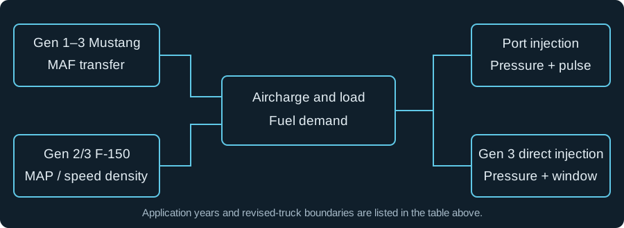
Swipe or use the arrow keys to read every label.
Load is a coordinate used by the calibration, not a direct measurement of engine health. Normalized cylinder aircharge, SAE calculated load and desired load are different quantities. Record the channel definition before comparing them. A naturally aspirated load above unity does not by itself prove a bad calibration.
- A meter correction also changes the aircharge represented to downstream control. Altering airflow just to move a torque limit changes what spark and cam tables see. Keep the measured-air model truthful, then investigate the remaining torque request or limiting source separately.
- On a MAF-equipped Mustang, an inferred pressure agreeing with another inferred quantity is not independent verification. Compare it with a calibrated physical pressure measurement when pressure is the question. On a speed-density truck, verify the physical MAP signal and its scaling before changing the model built on it.
Read the evidence before editing
Use a task-specific Scanner configuration and preserve the matching calibration revision. The Coyote logging procedure covers channel acquisition, unsupported parameters and external-sensor scaling. For airflow work, save each bank separately until agreement has been established.
| Capture | Useful agreement | Reason to stop correcting air |
|---|---|---|
| RPM, pedal, throttle, requested load and torque source | Operating state is repeatable | A different active limit or throttle intervention changes the sampled region |
| Active MAF signal and calculated air mass, on MAF applications | Axis signal updates through the visited cells | Stale axis, clipped signal or an inactive transfer |
| MAP, barometric pressure, temperature and actual cam position, on SD trucks | Sensor plausibility and comparable cam states | Wrong pressure scaling, cam tracking error or mixed mapped points |
| Commanded and measured lambda, feedback state, STFT and LTFT by bank | Repeatable correction with identified learning state | Bank split, misfire, transient enrichment or undefined trim math |
| Injector pulse, battery voltage and measured fuel pressure where available | Supply and voltage remain stable during the comparison | Pressure falls or pulse reaches a usable limit |
| Gen 3 Mustang/F-150 low-side and DI desired/actual pressure, PI/DI allocation | Both circuits support the requested fuel mass | High-side tracking alone hides missing low-side evidence |
A useful baseline repeats the same region after temperatures settle. A bad trace may look smooth but contain changing cam position, learned correction or pressure loss. An average cannot tell those causes apart. Review the time trace beside the histogram before using a cell.
Measured lambda following command does not prove the base model is correct when feedback is supplying the missing fuel. Conversely, an oxygen reading that appears lean can come from misfire or an exhaust leak. Resolve combustion and sensor problems before treating oxygen feedback as a fuel-flow measurement.
Enter complete injector characterization first
Low slope describes the model's low-fuel-mass region; it does not mean low rail pressure. High slope describes the higher-mass region. Breakpoint is fuel mass, while offset and minimum pulse are time quantities. A single advertised flow number cannot replace this dataset.
- Identify the installed injector. Record its exact part number and matching dataset. Stop if the only evidence is a seller's nominal flow rating.
- Match the pressure reference. Record whether the system holds rail pressure or differential pressure. Establish which pressure inputs are measured, assumed or inferred.
- Map each supported field. Record units for slopes, breakpoint, offset, minimum pulse and pressure compensation. Stop if the source and Editor representations cannot be reconciled.
- Enter the complete dataset in a copy. Compare every field with the source before writing. Reopen the saved file and check that small mass values retained their digits.
- Verify supply and short-pulse behavior. Check warm idle, accessory load, restart and light cruise. Stop for pressure loss, misfire or errors tied strongly to voltage.
- Then assess the remaining air error. Use repeatable conditions and both banks. Do not alter the MAF simply because the injectors changed.
Legacy Ford Editor labels include Injector Flow Rate Low, Injector Flow Rate High, Injector Breakpoint and Injector Pressure Drop Reference. They describe port-injector functions. Injector Offset vs. Voltage adds time; Injector Offset vs. Pressure is a multiplier on that offset. Injector PW Minimum is a duration.
These legacy labels do not establish the current Gen 3 direct-injector table names or units.
- Changing reference pressure requires a consistent model conversion. Copying slopes from a calibration normalized at another pressure while retaining the original multipliers can apply pressure compensation twice. Verify the whole relationship rather than choosing whichever combination gives a pleasing idle trim.
- Idle error that changes with electrical load suggests offset, voltage or supply deserves attention. Error that changes with commanded fuel mass suggests the short-pulse model deserves attention. These are diagnostic directions; neither pattern uniquely proves an injector parameter is wrong.
Correct a confirmed MAF configuration
This sequence applies to Gen 1–3 Mustangs and a Gen 1 F-150 whose MAF architecture has been confirmed. Read the active transfer, its axis and its units. A legacy voltage table appearing in the file does not prove it controls the frequency sensor.
- Resolve the baseline. Check fuel identity, intake and exhaust leaks, injector data and sensor installation. Stop for a bank-specific fault or unstable fuel supply.
- Build the graph on the active axis. Match Editor breakpoints and verify that the live axis moves. Stop if every sample falls in one cell because the input is missing.
- Choose a learning policy. Account for retained LTFT and residual STFT, or use a documented reset/disabled-learning method. Do not combine old learned values with newly reset data.
- Select stable samples. Exclude starting, fuel cut, rapid throttle motion and mixture transitions. Verify that the expected feedback is active in the sampled operating state.
- Resolve correction semantics. Determine whether the logged values are percentages, factors or another representation. Stop if the combined correction cannot be calculated from the channel definitions.
- Correct the visited region. A repeated fuel-add requirement supports increasing modeled air only after competing causes are excluded. A repeated subtract requirement supports reducing it under the same conditions.
- Inspect the resulting transfer. Check monotonicity against the axis direction: air rises with frequency and falls with period. Investigate isolated jumps. Leave unvisited cells identified as unverified.
- Repeat the comparison. Check the same conditions, neighboring cells, restart and transitions. Reject an edit that improves one average while worsening pressure, bank agreement or drivability.
Use partial corrections when the evidence supports a change but its magnitude remains uncertain. There is no fixed correction percentage or required iteration count. A noisy histogram does not become trustworthy because only part of it was pasted.
- Do not apply total fuel correction and residual lambda error independently without knowing their relationship. Feedback may already have corrected the lambda error. Adding the same error twice produces a new transfer error. Also check whether the selected command channel represents the base request or a controller-adjusted value.
- A plateau needs a separate diagnosis. Compare the raw sensor signal, transfer endpoint, calculated air mass and reporting channel. A display limit can flatten one trace, but that possibility does not establish that the physical sensor still has range.
Work on the F-150 speed-density model
Gen 2 F-150, 2015–2017, and launch Gen 3 F-150, 2018–2020, need pressure-based model work. Do not create a MAF correction graph merely because Scanner reports mass airflow. Keep the original file and document the supported model representation for the actual OS.
- Validate the pressure inputs. Check MAP against barometric pressure with the engine stopped, then check its response. Stop for a mismatched sensor or pressure unit.
- Separate cam states. Capture actual intake/exhaust position and mapped-point information where exposed. Do not fit one surface to samples from incompatible valve timing.
- Establish valid fuel error. Confirm injector characterization, fuel identity, feedback state and pressure. Stop if a fuel-delivery problem explains the correction.
- Inspect the model before generating changes. Identify the supported slope, offset, quadratic and blowthrough representation. Do not import coefficient recipes or parameter IDs from another tuning package.
- Review the generated file. Compare axes, units and changed cells with the saved original. Stop if a calculator changes an unrelated axis or creates an implausible value.
- Recheck model consistency. Assess aircharge, inferred quantities, torque response and throttle behavior across the affected cam states. Then revisit idle, restart and transitions.
The calculator presents a VE surface and converts its changes into model coefficients. A ten-percent fuel error does not mean multiplying every slope, offset and quadratic coefficient by 1.10. Their combined equation must describe the revised aircharge.
Keep the original cam coordinates and inspect the resulting surfaces as well as the individual coefficient tables.
- Blowthrough here describes air passing through during valve overlap; it is separate from a MAF installed after a compressor. A turbocharger alone does not establish a blowthrough setting. Check the model definition, actual cam positions and any supported exhaust-pressure input before changing that term.
- A reported Gen 2 2015 F-150 calculator problem changed an engine-speed axis unexpectedly. That single report does not identify every affected software build. It does justify comparing generated output before writing rather than assuming a successful calculation produced a valid file.
- There is no verified per-strategy coefficient recipe in this page. Use the definitions in the actual file and check the generated surfaces. If the available tool cannot represent the needed model consistently, retain the baseline and obtain the missing definition before proceeding.
Match the symptom to the next check
| Symptom and scope | Next evidence | Useful correction or boundary |
|---|---|---|
| MAF graph fills one cell, any confirmed MAF application | Actual axis source, units and live updates | Repair acquisition and graph setup before touching the transfer |
| Gen 2 2015 Mustang, LU47 change, different idle/cruise/load errors | Whole injector dataset, reference pressure, offset and learning | Reported data changes altered trims; no matched dataset proved a universal slope adjustment |
| Gen 2 2017 Mustang with truck manifold | Actual inlet and Mustang MAF response | Keep the car's air-model architecture; truck airflow tables do not transfer |
| Gen 3 2019 twin-turbo Mustang, midrange lean spike | Pressure units, compensation, allocation and torque/model agreement | A pressure-unit mismatch and disabled compensation were suggested; no single verified fix was established |
| Gen 3 boosted Mustang, port pulse stops increasing | Actual pulse versus allowed pulse, fuel allocation and pressure | Investigate the injection window; do not declare the injector static from a generic duty display |
| One bank requires more correction, all scoped applications | Leak, injector, sensor and combustion evidence by bank | A common air-model change cannot selectively repair one bank |
What the injector-data change actually established
The reported 2015 Mustang with LU47s ran different trims after replacing a Roush dataset with the part's characterization sheet. Higher-load correction improved while cruise still required fuel removal. That result identified a dataset-sensitive error; it did not finish the calibration. Offset and low-slope changes were suggestions, with no documented final repair.
Compare the entire pressure model before using either suggestion.
When throttle closure is covering a fuel shortage
- A boosted 2018 Mustang test retained commanded lambda while pressure fell because the controller reduced throttle opening and airflow. Correct mixture at the reduced airflow did not demonstrate capacity at the original request. The reported changes corrected low-pressure injector modeling and the throttle-body model while retaining fuel-capacity airflow intervention. Raising the capacity factor would have hidden the shortage. This was one tested calibration, not a pressure target or a part-number recipe.
- The useful result is often a narrower diagnosis. If a hardware or acquisition problem remains, preserve the air model. If injector data is unresolved, a tidy MAF curve merely records the compensation needed for that unresolved error.
Worked numbers with defined scope
A frequency-MAF axis conversion
For the frequency-MAF configurations above, period in µs = 1000 / frequency in kHz. Thus 5 kHz is 200 µs and 10 kHz is 100 µs. These are mathematical examples, not idle or load targets. Higher frequency means shorter period; the airflow transfer itself remains nonlinear.
LU47 port-injector data and unit checks
This example applies only to a compatible Gen 1/2 Mustang or F-150 actually fitted with M-9593-LU47 injectors. It does not describe factory injector equipment. Match the complete characterization and the pressure model before using any of these values.
| Item | Value | Entry check |
|---|---|---|
| High slope | 0.013005 lb/s | 46.818 lb/hr after multiplying by 3600 |
| Low slope | 0.014331 lb/s | Use the matched model, not a fixed ratio to high slope |
| Breakpoint | 0.0000130700 lb | Fuel mass, not pulse duration |
| Minimum repeatable pulse | 0.687 ms | 0.000687 seconds if the destination uses seconds |
Preserve the matching voltage-offset and pressure-compensation tables as well. The LU47 nominal rating is 47 lb/hr at 39.15 psi differential. Its published rating conversion to 43.5 psi is ×1.054, giving 49.538 lb/hr. That nominal conversion does not replace measured short-pulse data.
Why one pressure multiplier cannot replace the LU47 sheet
- At the sheet's 54.96 psid row, the high-slope multiplier is 1.1945. The modeled high slope becomes
0.013005 × 1.1945 = 0.0155344725 lb/s, or 55.9241 lb/hr. The low-slope multiplier is 1.1848, breakpoint is 0.9847 and offset is 1.2158. They are separate measured corrections. Applying the high-slope factor to every field would misdescribe this injector. - This is a check within the sheet's original reference model. Do not enter the pressure-adjusted high slope as the base slope and also retain that pressure multiplier. That would count the same adjustment twice.
Port-injector pressure under boost
- For any scoped PI system, injector differential pressure equals rail absolute pressure minus manifold absolute pressure. With both gauges referenced to the same atmosphere, gauge pressures can be subtracted too.
- Hypothetical Gen 1–3 Mustang/F-150 PI example: a fixed rail at 58 psig and manifold at 10 psig boost gives 48 psi differential. The first-order flow ratio is
sqrt(48/58) = 0.910. These are arithmetic inputs, not pressure settings. A steady rail gauge can coexist with falling injector differential.
Combining fuel corrections
- For any scoped application whose logged STFT and LTFT definitions are multiplicative percentage corrections,
total factor = (1 + STFT/100) × (1 + LTFT/100). Hypothetical +5% and +5% corrections give 1.1025. The arithmetic is confirmed; the channel definitions must still be checked in that vehicle. - Suppose a confirmed Mustang MAF cell contains 100 g/s. With valid +5% STFT and +5% LTFT, its full calculated correction is
100 × 1.1025 = 110.25 g/s. Change the airflow value at that signal breakpoint, not the frequency or period breakpoint itself. A partial correction still requires the same checks. - Opposite signs also matter: +8% LTFT and −4% STFT give
1.08 × 0.96 = 1.0368, a net 3.68% fuel addition. Do this calculation per bank before combining evidence. Averaging a positive bank correction with a negative one can hide a local fault.
A lambda error when feedback is absent
- For a valid steady sample with fuel feedback inactive, the fuel-demand factor is
measured lambda / commanded lambda. A command of 0.80 and measurement of 0.84 give0.84 / 0.80 = 1.05. That is five percent more fuel demand, assuming stable pressure and correct injector data. - Match the exhaust measurement to the earlier engine event after accounting for transport and sensor delay. This example explains the ratio; it does not call for disabling feedback. With feedback active, resolve its contribution before adding any residual lambda error.
Gen 3 port plus direct-injection capacity
For Gen 3 Mustang, 2018–2023, and launch Gen 3 F-150, 2018–2020, treat port delivery and direct delivery as separate characterized paths. Low-side supply also feeds the high-pressure pump. A port injector upgrade cannot independently prove that both circuits have adequate supply.
- Identify allocation semantics. Read the exact blend definition, mode and units. Stop if the table's percentage direction or active operating condition is unresolved.
- Compare both pressure paths. If DI pressure drops, determine whether low-side supply fell first. Stop if the only available low-side value is a target or inference.
- Separate pressure shortage from time shortage. Pressure holding while injection duration reaches its usable window suggests a different constraint from pressure failing to track demand.
- Check the receiving path. Moving fuel demand toward PI requires port pulse capacity, correct characterization and low-side reserve. Stop when the receiving path cannot deliver the requested mass.
- Keep fuel-capacity intervention meaningful. An airflow limit disappearing after a capacity-factor change does not establish more delivered fuel. Verify lambda, pressure and actual pulse behavior.
For these Gen 3 applications, four-stroke cycle time in milliseconds is 120000 / rpm. At a hypothetical 7500 rpm, a cycle lasts 16 ms. A single 12 ms PI pulse occupies 75% of that cycle. This calculation is not a stock pulse limit.
- DI's usable injection interval occupies only part of the cycle. A duty display based on the entire cycle cannot establish remaining DI time. Port timing constraints can also restrict usable duration before a full-cycle duty display reaches its endpoint. Account for multiple pulses when the strategy uses them.
- At 6000 rpm, one crank degree lasts
60000 / (6000 × 360) = 0.02778 ms. A hypothetical DI window spanning 180 crank degrees therefore lasts 5 ms. That window would last 4 ms at 7500 rpm. These spans are arithmetic examples, not usable angle settings. The same allowed crank-angle span gives less injection time as rpm rises, even with pressure on target. - No universal PI minimum share, DI pressure ceiling or injection-angle recipe follows from these examples. Extending an angle limit requires verified angle reference, event meaning and combustion consequences. Lowering DI pressure to make actual follow target can reduce injector flow and use more of the available window.
Questions about Coyote airflow and fuel
Why doesn’t a Mustang MAF curve work on my F-150?
Gen 2/3 F-150s in the application table use measured manifold pressure and a speed-density model. Their calculated air mass is not a physical meter signal. A Mustang transfer maps its meter and inlet geometry to mass flow, so there is no equivalent truck correction cell to paste into.
A truck manifold installed on a Mustang does not convert the car to the truck strategy either. Confirm the original architecture before choosing graph axes or tables. For a Gen 1 truck, verify the actual MAF hardware and active strategy before using the Mustang correction sequence.
What do I tweak to get trims back after an injector change?
Start with the entered injector dataset and its pressure reference. Compare slopes, breakpoint, minimum pulse, voltage offset and pressure compensation with the installed part's characterization. Then check measured supply and fuel identity. A correction that changes strongly between idle and cruise deserves short-pulse and offset investigation before a MAF edit.
The reported Gen 2 LU47 case changed behavior when different data was entered, but it did not establish a percentage adjustment for other cars. Once the complete injector model is consistent, use remaining repeatable error to assess the air model.
Do I type the injector sheet in as-is or scale it for pressure?
Use a dataset and pressure model that share the same reference. If the source matches the destination representation, enter the matched characterization with its compensation. If the existing file uses a different normalization, reconcile the whole model before combining them.
A flat pressure ratio is not a valid flow conversion, and a square-root flow estimate does not replace offset or breakpoint compensation. Check what pressure the PCM measures or assumes. A calibration that idles acceptably can still contain two errors compensating for each other, so idle trims alone cannot validate the conversion.
Does the engine even measure fuel rail pressure?
Identify the actual sensor and the selected channel. Some Gen 2 configurations expose inferred pressure, so a graph labeled fuel pressure can describe the model rather than measured delivery. When pressure is not measured by the vehicle, use suitable independent instrumentation to answer the supply question.
On Gen 3, distinguish DI rail measurement from low-side feed and port-injector differential pressure. They describe different locations and constraints. A desired value shows controller intent. An inferred value shows an assumption. Neither independently proves that the pump delivered that pressure throughout the event.
What is the PCM doing with PFI Injector Maximum Pulse?
First confirm whether the parameter reports a permitted duration or a calibration limit in the selected strategy. Compare it with actual port pulse, engine speed and fuel allocation. A flat actual pulse against a flat allowed duration can explain why added demand no longer produces more port fuel.
The reported Gen 3 boosted cases describe this behavior, but they do not establish one universal duty ceiling. The cycle-time calculation above only supplies a reference for interpreting duration. Extending a limit without resolving timing constraints and fuel delivery does not establish usable injection capacity.
If the blend cell is 100, is that all direct or all port?
Do not infer direction from the number alone. Identify the exact HP Tuners parameter, percentage definition, mode and active table. Gen 3 calibrator descriptions often express allocation as direct share, but that convention does not verify every displayed blend parameter. Confirm the interpretation against supported PI/DI delivery channels and pressure behavior.
A screenshot from another tuning package cannot settle the mapping. There is also no established universal minimum port share in this material. Preserve the working allocation until characterization, supply and usable injection windows support a specific change.
Is the learned trim the same everywhere?
Learning and feedback are operating-state dependent. Check the active feedback mode and the definitions of the selected learned and short-term channels. Do not assume that values retained at idle apply unchanged to another load region, or that enrichment always disables feedback.
Record the learning policy with the log so a later correction uses the right baseline. After resetting learning, collect new stable evidence rather than applying an old histogram. When lambda already follows command through active correction, account for that correction once.
Otherwise the next airflow edit can duplicate an error the controller already removed.
What is the limit of STFT and LTFT before a light?
The diagnostic threshold belongs to the matching strategy and its enable conditions. Read those definitions from the file and supported diagnostic information rather than using a universal trim percentage. A value below a fault threshold is not automatically an acceptable calibration result. Assess repeatability, bank agreement, pulse behavior, voltage and pressure reserve.
A small average can hide a large error during a transition or a supply problem at another load. Correct the cause when it is established, and preserve unresolved regions as gaps instead of declaring the whole fuel system healthy.
Why is low slope higher than high slope?
The names identify regions of commanded fuel mass, not two pressure settings. A slope is one part of a piecewise delivery model. Breakpoint and offset determine how those regions join and how pulse duration is calculated. The LU47 sheet itself has a higher low slope.
Do not reverse the values to make the names seem logical, or impose a fixed difference between them.
Which speed-density tables do I touch, and do I enable blowthrough?
Identify the active mapped points and the calculator representation supported by the truck's actual file. Revise the represented breathing surface, then review the generated coefficients. Blowthrough accounts for overlap flow; it is not a turbo enable switch. A correction that changes with cam position needs evidence at those cam states.
A single fuel-trim histogram cannot identify every coefficient or justify copying the same change through every mapped point.
Why is there a no-fly zone for port injection angles?
A port pulse has timing constraints as well as a full-cycle duty calculation. Permitted start and end timing, valve events and strategy limits can shorten the available interval. Compare actual pulse with the reported allowed pulse and the active timing limits.
A flat pulse while fuel demand rises is more useful evidence than a generic duty percentage. Extending an angle boundary needs its reference and event definition; another car's duty ceiling does not supply them.
Why didn’t changing ethanol stoich fix my rich idle?
The reported Whipple F-150 remained rich after two different stoichiometric entries. That result did not establish the correct fuel composition or a final repair. Check actual fuel identity, injector characterization, learning, combustion and pressure first. Changing stoich affects fuel demand across operating regions; it cannot isolate an idle-only error.
Use lambda to compare command with measurement, and keep a gauge's selected AFR display scale separate from the PCM's fuel model.
After airflow and fuel delivery agree with the evidence, continue to Coyote spark and knock; its load coordinates depend on this work.
The free Tune Report reviews a readable calibration and matching log, including unresolved measurement gaps.
Ford Full Custom is open at $199 during the launch special ($249 regular). Every file is compared against our 3 million+ tune values, with a final check-off by our lead tuner. The guides and free checks are open now. Order Ford Full Custom for your Coyote.
Tune Report is free if you want this file checked: open the Ford Tune Report.
A written review of your tune file and one log from your car.
Start a Ford Tune Report