
VTC cam angle and VTEC engagement on a K20 or K24
Published
A cam target is a position request in crank degrees. The VTEC bit is a solenoid command. This guide covers port-injected K20 and K24 engines on KPro and FlashPro. It shows how the target is built and how the phaser tracks it. It also shows how the lobe switch is set and what the log must show before either number changes.
- VTC moves the intake cam continuously. VTEC changes the lobe. They meet at the crossover, but they are separate systems.
- Hondata measures cam angle in crank degrees. A 50 degree crank target is 25 degrees of camshaft rotation.
- KManager's tuning steps use cam angles at 0, 10, 20, 30, 40 and 50. Current FlashPro help describes five copies and a 0 to 45 or 0 to 50 range. Read your calibration.
- A 25 degree target move takes about 0.25 second at 10 degrees per 0.1 second. The phaser cannot jump at the switch.
- A VTEC command bit, a pressure switch and a torque change are three different pieces of evidence.
- The installed stop and measured clearance set the travel limit before target tuning begins.
Most VTC and VTEC mistakes start with a request that was never checked against the mechanism. A tuner types 50 degrees into a high-cam table, and the log stops at 45.
Or the VTEC bit turns on, the engine note changes, and the car is slower because the cam was still moving into position.
This page separates the request from the actuation. It covers the target tables, the phaser, the lobe switch, the log channels and the checks that stop a bad edit. Fuel and ignition changes at each angle belong to the fuel and ignition pages.
Full Custom: $249 $199 launch special. Most files in 3–5 business days after complete inputs; the outside limit is 7 business days.
Port-injected K20 and K24 only. The turbo Civic is the separate turbo section on the same Honda & Acura hub. Hondata or FuelTech hardware and credits are not included. How files are handled.
1. The boundary: port-injected K20 and K24
The procedure applies to the port-injected K20 and K24 engines in the table below.
- The year and chassis get you close. The ECU, the calibration and the installed hardware decide what the tables mean. A K20A3 or K24A4 economy head is a different valvetrain, and its crossover numbers do not transfer. The K20C, L15, K24W direct-injection Accord, B-series, D-series and s300 are outside this page. FuelTech runs VTC with its own settings, and those settings do not copy from a KPro table.
- The page does not print a target map, a piston-to-valve clearance or a VTEC oil pressure in psi. Software permission does not establish valve train clearance. A builder's measurement and stop decide that.
| Engine and vehicle | Software route | Cam authority to check |
|---|---|---|
| K20A2, 2002–2004 RSX Type S | KPro in an eligible PRB ECU | 50 degree mechanism; read the calibration's allowed maximum |
| K20Z1, 2005–2006 RSX Type S | KPro on a specially modified 2002–2004 ECU with the chassis-specific adapter | 50 degree mechanism; use the earlier primary O2 sensor; the original 2005–2006 ECU is not the donor |
| K20Z3, 2006–2011 Civic Si | FlashPro on the RRB or RRD ECU | 0 to 50 or 0 to 45, depending on calibration type |
| K20A, JDM Integra Type R and Civic Type R | KPro on the matching ECU | 50 degree mechanism; confirm the ECU and market; on JDM engines and JDM ECUs, disable the VTEC oil pressure sensor |
| K24A2, 2004–2006 TSX | FlashPro conversion with a 2007–2008 ECU, wiring adapter and immobilizer | 25 degrees stock; any larger gear needs a measured clearance limit and a physical stop |
| K24A2, 2007–2008 TSX | FlashPro on the supported TSX ECU | 25 degrees stock; any larger gear needs a measured clearance limit and a physical stop |
The TSX rows are the ones that catch people. A 2004–2006 car needs a FlashPro conversion: a 2007–2008 donor ECU, a wiring adapter, the immobilizer, the transmission program and CAN. It is not an OBD-port flash.
More details
- A 2007–2008 car is the donor generation and runs FlashPro on its supported ECU. Buying for a 2004 as if it were a 2008 is the mix-up. The older KPro test on a 2005 TSX used an RSX ECU and adapter for dyno work. The cluster, air conditioning and stability assist did not work. It is not a street route beside FlashPro.
- The 25 degree stock travel can stay on a 2004–2008 K24A2. A 50 degree table target on a stock 25 degree actuator does not create travel. A 50 degree target on a modified engine still needs the physical stop and clearance check.
- The JDM note is a calibration instruction. KManager's VTEC page says to disable the VTEC oil pressure sensor for JDM engines and JDM ECUs. That is not a psi threshold and does not make the pressure switch a tuning target.
2. The VTC phaser and the VTEC lobe switch
VTC is continuous. Oil pressure acts on a vane inside the intake cam sprocket, and the ECU trims a solenoid to hold a target angle. The cam moves through a range instead of switching between two fixed positions. On the K20A2 the range is 50 crank degrees.
On the stock K24A2 it is 25 crank degrees.
- VTEC is switched. The ECU fires a solenoid, a spool valve sends oil to the rocker shafts, and pins lock the rocker arms to a higher-lift lobe. On the K20A2 head there are three lobes per pair of valves on both the intake and exhaust cams. The K20A3 head has no VTEC on the exhaust side, which is one reason its behavior is not a small K20A2.
- The two systems share the intake cam but not the same failure path. VTC can track while VTEC never engages. VTEC can engage while the cam is at the wrong angle, or while it is still moving into position.
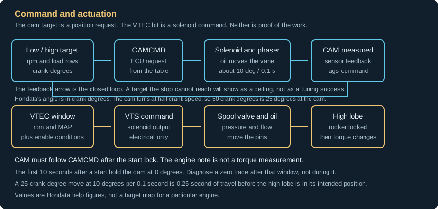
Swipe or use the arrow keys to read every label.
More details
The feedback loop is the important part of the diagram. CAMCMD comes from the target table and the running conditions. CAM is the measured result. The phaser has to move the cam, the sensor has to report it, and the ECU has to correct the solenoid.
A target that the stop cannot reach will show as a flat ceiling. A target that the phaser can reach will show as a short lag and then a settle.
3. Crank degrees and the mechanical stop
Hondata measures the intake cam advance in crank degrees. That is not the same as camshaft degrees. The cam turns at half crank speed, so 50 crank degrees is 25 degrees of camshaft rotation. A 25 crank degree move is 12.5 degrees at the cam.
This matters when a builder talks about a cam card or a piston pocket in cam degrees.
- KManager's cam-angle page gives an allowable range of 0 to 50 degrees. The current FlashPro VTC page gives 0 to 45 or 0 to 50, depending on the calibration type. The calibration you opened decides which limit applies. Read the maximum from the table axis and the help for that calibration before you type a number from another car.
- The stop is physical. Hondata's help is explicit that Honda cams have a stop to prevent valve-to-valve and valve-to-piston contact, and that aftermarket cams are the manufacturer's responsibility. The same help warns that limiting the cam position in the ECU does not ensure the cam will stay within that limit. A software cap is not a physical stop. VTC changes valve timing; it does not increase the lift of the selected lobe.
| Number | What it describes | Where to confirm it |
|---|---|---|
| 50 crank degrees | K20 VTC mechanism travel and a common table maximum | The calibration axis and the cam mechanism, not a target by itself |
| 25 crank degrees | Stock K24A2 TSX VTC travel | The TSX calibration and the installed mechanism |
| 45 crank degrees | An example of mechanically limited travel on a modified gear; not a clearance specification | The actual stop and builder's clearance check, not a general K24 rule |
| 0 degrees | Fully retarded position and the start lock | The CAM channel after the first 10 seconds |
A cam target is a request. The cam lobes, valve timing, pistons and installed geometry decide what clears; the stop limits travel. If the clearance is unknown, do not run a maximum-angle sweep to find out. Establish clearance and the physical travel limit before testing.
4. The target map and the table copies
The Cam Angle target map has a low-cam table and a high-cam table. Each is indexed by rpm and load. The ECU reads the active table, adds the running-condition corrections, and produces CAMCMD. The phaser then chases CAMCMD. The target is not one number for the whole engine.
Their torque-optimal values can differ at the same rpm; the transition still needs a workable blend.
More details
The angle-indexed MAP fuel and ignition tables are split by lobe and by cam angle. KManager's help describes six fuel and six ignition maps per lobe. The breakpoints are 0, 10, 20, 30, 40 and 50 degrees, and the ECU interpolates between them.
The current FlashPro VTC page describes five copies at 0, 15, 30, 40 and 50 degrees. It gives an allowed range of 0 to 45 or 0 to 50. Both descriptions are real for their software and calibration. FlashPro's tuning overview also lists a 0, 10, 20, 30, 40 layout.
Read the calibration rather than assuming either layout applies.
On FlashPro, confirm Fuel Table Type first: AFM-based fueling does not use the MAP fuel tables. The angle-blend examples below apply to angle-indexed tables. At a steady 24 degrees on a KPro layout, the angle blend is 60% from the 20 degree table and 40% from 30.
On a FlashPro layout with 15 and 30 degree breakpoints, the weights are 40% and 60%. Read the actual CAM value from the log, then find the tables that bracket it. These weights describe only the angle axis at matching rpm and load.
The ECU also interpolates across the rpm and load axes.
Part throttle is part of the target map, not a separate economy map. KManager's guidance puts idle below 1,000 rpm at 0 or 5 degrees. Cruise at 1,500–4,500 rpm sits near 30 degrees.
Above normal cruise rpm, the guidance uses the full-load angle to avoid a phase drop during a shift. The FlashPro VTC help gives 15 to 30 degrees for the cruise region at columns 2 to 7.
Overlap at cruise is deliberate, and the cam should not swing back to zero every time the throttle closes.
| Region | What the target is doing | What the log should show |
|---|---|---|
| Idle, below 1,000 rpm | Near 0 degrees, or 5 degrees on some guidance | CAM near the target after the start lock, stable, no hunting |
| Cruise, 1,500–4,500 rpm | KManager guidance: near 30 degrees; FlashPro guidance: 15 to 30 degrees | CAM follows the target at steady load, no surge or lean step |
| Decel and fuel cut | Return to 0, hold an intermediate angle, or follow the tables | The choice in the calibration matches the CAM trace and the next gear |
5. Read the cam and the switch
The minimum log is rpm, manifold pressure, the intake cam actual and command, VTEC command, lambda and spark. KManager names that pair CAM and CAMCMD. FlashPro's sensor list for the Civic Si and the TSX names the same pair VTC Actual and VTC Cmd.
More details
The help topic is still titled CAMCMD. Use the pair the open calibration actually logs; a missing CAM channel does not mean the phaser is not logging. Add coolant temperature, intake temperature, vehicle speed, oil pressure if available, and the VTEC pressure switch if the calibration exposes it. The logging guide covers the export and channel setup. This page covers the cam and switch traces.
CAM is the measured intake cam position in crank degrees; FlashPro calls it VTC Actual. CAMCMD is the desired position; FlashPro calls it VTC Cmd. Hondata's KManager help states that the actual cam can lag the command by 0.1 to 0.5 seconds.
The mechanism is a closed loop, so a short lag during a step is normal. A permanent offset, a flat ceiling or an oscillation is not.
The first 10 seconds after a start are a lock, not a fault. KManager's CAM channel definition says the intake cam is held in the zero, fully retarded position for the first 10 seconds after startup. The FlashPro VTC page words it as a hot start.
Let the engine run past that window before you diagnose a zero trace. If CAM stays at zero after 10 seconds at a warm idle, check the solenoid, oil supply, actuator and sensor. The target must be above zero.
VTEC is not an rpm-only switch. The FlashPro VTEC parameters page describes a window based on rpm and manifold pressure, plus coolant temperature and vehicle speed. High load can occur below full throttle, so a part-throttle log can still show the switch. The command bit records the ECU request to the solenoid.
The pressure switch is a second signal. Neither proves the rocker pin moved.
| Log observation | What it establishes | Next check |
|---|---|---|
| CAM follows CAMCMD after a step, with a short lag | The phaser is moving and the sensor is reporting | Check the settle, the ceiling and the torque at that angle |
| CAM stops at 25 degrees on a 50 degree target | A mechanical or calibration ceiling, not a PID tuning opportunity | The installed gear, the stop, the table axis and the sensor zero |
| CAM oscillates around the target | The loop is not settling, or oil supply and mechanics are unstable | Oil, solenoid, actuator, timing and wiring before gains |
| CAMCMD steps 25 degrees at the switch and CAM arrives late | The target changed faster than the phaser can travel | Pre-advance the low cam and re-index the rows around the switch |
| VTEC bit on, no torque or pressure change | The ECU requested the solenoid; output voltage and rocker movement remain unverified | Oil pressure, spool valve, pins and the pressure switch |
Stop if CAM does not follow CAMCMD at a steady target. Stop if the cam hits a ceiling below the command. Stop if a cam phase code is present. Stop if oil pressure is low or the timing chain is suspect.
A new target on a mechanism that cannot track is a request for a number the engine will not deliver.
6. Set the cam target from a measured result
The target angle is a compromise between overlap and the rest of the engine. Advancing the intake cam opens the valve earlier and adds overlap. More advance helps midrange cylinder filling on a naturally aspirated K with a free-flowing exhaust.
Too much at high rpm can hurt the top end, and a turbo with high exhaust backpressure wants less advance, not more. The direction is a hypothesis until the torque at that rpm and load says otherwise.
The method is to hold one angle, check the fuel and spark at that angle, record torque, and repeat at the angles the calibration exposes. The fuel and ignition work belongs on the other pages.
Here the check is narrower: did the cam actually hold the angle you asked for, and did torque improve at the same rpm and load? A row that looks smooth is not a result.
- Identify the head, the cams, the phaser and the software. Record the engine code, the ECU, the calibration, the cam manufacturer and the installed stop. Confirm the timing chain, the oil condition and the cam sensor before a pull. If the clearance is unknown, keep the test inside the range the builder will sign for.
- Save the as-found calibration and take a warm baseline. Log idle, cruise and a load sweep after the 10 second start lock. Confirm CAM follows CAMCMD at a steady target. Confirm the VTEC bit changes where the window says it should, and confirm the pressure switch if the channel exists.
- Hold a safe angle and check the supporting tables. Use Lock VTC as a test control on KPro. On FlashPro, use a constant target in the active cam-angle table and verify actual phase. At the held angle, confirm actual phase has settled, lambda follows target and spark is stable. If any of those checks fail, fix the cause before comparing torque. A lean angle can lose torque for a reason that has nothing to do with cam phasing.
- Record torque at each angle the calibration exposes. Use only breakpoints inside the measured travel limit; skip unreachable or uncleared angles. Compare at the same rpm, load, temperature, fuel and acceleration rate. Keep the angle that carries the most torque at that address. Do not copy a row from another engine because it looks smooth.
- Build the low-cam and high-cam targets separately. The optimal low-cam angle and the optimal high-cam angle at the same rpm can be far apart. The engine changes its breathing when the lobe changes. A low-cam result is not a high-cam result.
- Bracket the chosen angle. Move a small amount either side and repeat the torque check. Hondata's help suggests a 5 degree bracket around the composite map, then a 2 degree check if the curve is close. Keep every test inside the measured clearance range and software limits. At a 45 degree physical limit, a 45 degree target leaves no room for a positive bracket.
- Restore the variable targets and check the transitions. A fixed-angle result is not a finished schedule. Put the target map back, then log the move between angles, the switch, a shift and a decel. A schedule that only works on a slow sweep is not validated.
7. Set the VTEC point and the window
The VTEC point is the rpm where the high-cam torque curve crosses above the low-cam curve. Below that point the low lobe makes more torque. Above it the high lobe does. The correct point is the intersection, not the rpm where the sound changes.
A harder kick usually means the engine stayed on the weaker lobe too long.
More details
Compare low-cam and high-cam runs with fuel, spark and phase already checked on each lobe. Move the switch within the applicable limits and record only the rpm range needed to bracket the expected intersection. Do not hold the low cam to redline to finish the comparison.
Overlay the two curves at the same rpm and load. The crossing is the starting point. Bracket it in 100 rpm steps and keep the most torque through the transition. A small dip is normal. A large dip means the point or the cam blend is wrong.
| Application | Documented point | What the number is |
|---|---|---|
| Hondata general guidance, stock engine | 5,500–5,700 rpm | A general example, not every factory K24 switch |
| Hondata general guidance, intake and exhaust | 4,500–4,800 rpm | A general example, not a finished bolt-on preset |
| Hondata general guidance, supercharged | 3,000–3,200 rpm | A general example, not every turbo or blower K |
These ranges describe general combinations. Aftermarket cams, a different header or a turbo can move the intersection. Use the two torque curves rather than transferring a reflash point from another car.
More details
The bounds are separate from the optimum. KManager gives 2,000 rpm as the low guide and 6,500 rpm as the high guide. The FlashPro VTEC parameters page gives 2,500 rpm for a twin-cam engine and 6,500 rpm as the ceiling.
For this procedure, stay between 2,500 and 6,500 rpm unless the build requires a narrower range. These guide values do not certify an aftermarket valvetrain. Below the floor the oil pressure may not support the rest of the engine.
Above the ceiling the high-speed rocker can float and damage the valve train. These are warnings, not targets.
The window is not a second rev limiter
More details
The VTEC window uses rpm and manifold pressure. The lower boundary is the point you found at high load. The upper boundary is a higher rpm for lighter load. It does not switch VTEC off above that rpm; the main rev limiter remains separate.
Hondata's setting steps use 6,000–6,500 rpm at the top. The naturally aspirated example uses 80 kPa up to the lower rpm, falling to 40 kPa at the upper rpm. These are absolute manifold pressures, not boost-gauge readings. Smooth the pressure between the points.
More details
The boost guidance on that help page gives two different starting ranges. Its numbered steps specify 110–120 kPa at the lower rpm. Its separate forced-induction paragraph specifies 120–150 kPa there, falling to 70–80 kPa at the upper rpm. Those are separate examples, not one combined prescription.
Choose the window from the engine's load-dependent crossover and verify it in the log.
Pre-advance the cam before the switch
More details
The cam cannot jump at the switch. Hondata's crossover page gives the worked example. The switch is at 4,350 rpm, the low-cam target is about 12 degrees, and the high-cam target is about 37 degrees. The move is 25 crank degrees.
At 10 degrees per 0.1 second it takes about 0.25 second. The help rounds the theoretical move to about 0.3 second. Its separate pictured log moves from 26 to 50 degrees in about 0.3 second.
During that time the engine is on the high lobe at the wrong angle.
More details
The fix is to start moving the cam on the low-cam table before the switch. Set the low-cam target at the higher row to the high-cam angle at the same rpm. The phaser is then near the new position when the lobe changes.
The car gives up a little low-cam torque before the switch and gains it back after. Hondata's example uses 4,200, 4,300 and 4,400 rpm rows for a 4,350 rpm switch. Those rows are an example, not a required axis.
Re-index the rows around the switch so the move happens over a short interval. Do not let the high-cam angle drop toward zero across the switch rows, or the cam retards during a shift. Remove rows the high cam never uses and put the resolution where the cam moves.
Check that the resulting torque curve improves through the switch. Re-indexing alone does not prove the cam arrived in time.
For a separate timing example, suppose the targets step from 30 to 48 crank degrees. The nominal travel time is 18 ÷ 10 × 0.1 = 0.18 second. At 1,000 rpm per second, the engine gains 180 rpm during that move. At 2,000 rpm per second it gains 360 rpm.
These are illustrative rates, not measured K-series results. A ramp spanning 150 rpm would allow only 0.15 or 0.075 second at those rates. Check elapsed time and actual phase before choosing how early the ramp starts.
8. When the cam or the switch does not track
Diagnose in the order of the mechanism. First confirm the engine is past the start lock and the ECU has enabled VTC. Then compare CAM with CAMCMD. A short lag during a step is normal. A sustained ceiling near 25 degrees on a 50 degree target suggests limited travel.
Confirm the gear, calibration limits and sensor plausibility before assigning the cause or changing PID gains.
More details
A brief full-advance spike after a cold start can be the ECU's VTC cleaning cycle. FlashPro help describes overrun pulses near 2,000–3,000 rpm, about five seconds after throttle release, with logged spikes to 45 or 50 degrees. Match that pattern before calling it a control fault.
It also explains why a limited target map cannot replace a mechanical stop on an engine that cannot clear full gear travel.
If the trace oscillates or sits permanently offset, check the mechanical timing, oil supply, solenoid, filter, actuator and sensor wiring before you change the controller. A cam phase code is a clue, not an obstacle to delete.
KManager's VTEC page describes P0341 as an intake-to-exhaust phase error of more than about 5 degrees. That is a fault description, not a 5 degree VTC target limit. It also states that some aftermarket cams will set it.
The answer is to verify the mechanical timing and the actual phase, not to switch the check off.
If VTEC does not engage, check the conditions before the calibration. Oil level and temperature, coolant temperature, vehicle speed and manifold pressure all affect the switch. The solenoid and spool valve can seize, and the screen can clog. The pressure switch circuit can set a code.
A car that pulls cleanly to redline with no switch may have a hardware or condition fault, not a table that needs a lower number.
| Symptom | First read | Not the fix |
|---|---|---|
| CAM stuck at 0 after a start | The 10 second lock, then CAMCMD, oil and the sensor | Replacing the solenoid before the lock expires |
| CAM stops below the command | The installed gear, the stop, the table axis and the sensor zero | Raising PID gains or the target |
| CAM oscillates at a steady target | Oil supply, solenoid, actuator, timing and wiring | A gain change to hide a mechanical fault |
| Dip or surge after the switch | The CAMCMD step, the CAM lag and the two torque curves | Moving the switch without fixing the blend |
| VTEC bit on, no change | Oil pressure, spool valve, pins and the pressure switch | Treating the bit as proof |
| P0341 after a cam install | Mechanical timing and actual intake to exhaust phase | Deleting the check |
| Switch later than the rpm table | Manifold pressure, coolant and speed at the switch | Lowering the rpm cell blindly |
9. Numbers used on this page
None of these is a target for your engine unless the row says so. The application column is part of the number.
| Quantity | Value | Applies to | What it is |
|---|---|---|---|
| Cam angle unit | Crank degrees | Hondata KPro and FlashPro | 50 crank degrees is 25 degrees of camshaft rotation |
| KManager cam range | 0 to 50 degrees | KManager, VTC K-series | Software range on the cam-angle page |
| FlashPro cam range | 0 to 45 or 0 to 50 degrees | FlashPro, calibration-specific | Read the allowed maximum for the calibration you opened |
| K24A2 TSX stock travel | 25 crank degrees | 2004–2008 TSX K24A2 | Stock mechanism, not a target for a modified engine |
| Example modified-gear stop | 45 crank degrees | Mechanically limited gear | Verify the stop and clearance; 45 is not a universal safe limit |
| Start lock | 10 seconds at 0 degrees | KManager CAM channel; VTC tuning help | CAM definition says startup; tuning help specifies a hot start |
| Phaser rate | About 10 degrees per 0.1 second | K-series VTC | Travel rate from Hondata's help |
| Command lag | 0.1 to 0.5 second | K-series VTC | Actual CAM can lag CAMCMD |
| Crossover example | 4,350 rpm, 12 degrees low, 37 degrees high | Hondata's worked example | 25 degree move: 0.25 second by the stated rate; rounded to about 0.3 in the theory |
| VTEC low guide | 2,000 rpm KManager, 2,500 rpm FlashPro twin-cam | K20 and K24 | Warnings, not targets; use 2,500 as the working floor |
| VTEC high guide | 6,500 rpm | K20 and K24 | Engagement-point warning, not an engine rev limit or target |
The numbers have different jobs. A mechanism rating, a stock switch point, a reflash point, a general example and a warning bound cannot be swapped. Read factory and reflash switch points from the specific calibration; the general ranges above do not identify them.
Questions
Does the VTEC light mean it switched?
No. The light or the VTS channel shows the ECU command. The spool valve still has to move, the oil pressure has to be enough, and the pins have to lock the rockers. CAM reports intake phase, not the rocker-pin position.
Compare torque response with the command and pressure evidence; investigate the hardware if they disagree. If the command is on and the engine does not change, diagnose the hydraulics before the table.
Is 50 degrees safe?
The crank-degree scale does not establish clearance. A larger K24 gear needs a physical travel limit chosen for the actual cams, pistons and installed geometry. A 45 degree stop is not automatically safe either. Measure clearance across the required travel on both lobes before choosing the stop.
Why does the cam read 0 degrees after a start?
The intake cam is held in the fully retarded position for the first 10 seconds after a start. That is a documented lock, not a failure. Let the engine run past the window and check again at a warm idle with a target above zero.
If CAM stays at zero after that, check the target, the oil supply, the solenoid, the actuator and the sensor.
Why will the cam not go past 25 degrees?
Check the installed mechanism, stop and calibration limits. The stock K24A2 TSX gear is nominally 25 degrees; a higher target cannot turn it into a 50 degree gear. A 30 degree request in an old file does not identify the hardware. Read actual phase and inspect the part before changing controller gains.
Why does the engine dip after VTEC?
Compare actual phase with command before blaming the switch point. If phase arrives late, work on the pre-advance blend described above. A lean stumble also needs a fuel check at the angles actually traversed; matching the endpoint targets does not finish those tables.
If phase tracks and the separate torque curves show the high lobe was selected too early, try moving the point higher in 100 rpm steps. Hondata describes a small dip under about 5 lb-ft as normal in its example. That does not excuse a lean event, misfire or unresolved phase error.
Does E85 change the cam angle?
Ethanol does not change mechanical clearance, so it does not make a 50 degree target safe on an engine that cannot clear it. It can change the torque and knock limits under which the angle is evaluated, so the composite map may need a recheck. There is no universal ethanol cam adder.
Treat the fuel change as a reason to repeat the torque check, not as a reason to add advance.
Why does P0341 appear after a cam install?
KManager associates the code with an intake-to-exhaust phase error of more than about 5 degrees. That is a reason to verify the mechanical timing and the actual phase, not a reason to delete the check.
If the cams are degreed correctly and the phase is within the intended range, then the calibration and the sensor circuit are the next checks.
Can I lock VTC at one angle?
Lock VTC is a test control. On KPro, it fixes the command so you can check fuel, spark or torque at one angle. FlashPro's tuning procedure instead makes the active cam-angle table constant. Both still require an actual-phase check.
A fixed angle gives up the midrange-to-top-end trade that the target map is for. It also cannot establish that a modified engine is ready to drive to a tuner. Clearance, fuel and spark still need checking.
Does the ECU interpolate, or do I fill only the nearest angle table?
It interpolates. On a KPro layout, 47 degrees uses 30% of the 40 degree table and 70% of the 50 degree table. Editing only the nearest table leaves the other contributor unchecked. Tune both reachable neighbors and confirm the blend.
Copying a tuned angle into the remaining tables is an initial estimate, not a completed map.
Can I limit VTC in KManager and skip the pin?
A target limit cannot replace a physical stop. The closed loop can overshoot, and the ECU can request a cleaning sweep outside the normal target schedule. A correctly installed limiter or a gear with restricted travel addresses that mechanical limit. Choose its travel from measured clearance, including both lobe profiles.
The low lobe clears at 50 degrees but the high lobe does not. Can I still use it?
The phaser has the same physical travel on both lobes. Keeping a dangerous angle out of the high-cam table does not provide clearance during an unexpected transition. The stop must keep the mechanism within the measured safe envelope for both profiles.
A cam brand or stage number alone does not supply that measurement.
Why does it sweep to 50 degrees at light load?
Check whether it is the cold-start cleaning pattern described above. A brief overrun sweep can be expected ECU behavior. A sustained tracking error, a phase code or repeated spikes outside those conditions still needs diagnosis.
A normal cleaning request can remain mechanically unsafe on an engine whose replacement gear has too much travel.
Can I keep VTEC out while cruising on the highway?
Use the load window rather than raising the lower rpm everywhere. KManager's example spans 3,800 rpm at 96 kPa to 5,500 rpm at 30 kPa. At 4,650 rpm, its linear pressure boundary is 63 kPa absolute.
A steady 50 kPa cruise is below that boundary; a hill raising MAP to 80 kPa crosses it. That assumes the temperature and speed conditions are also met. Log the actual cruise load before changing the upper boundary, and retain enough high-load access to the stronger lobe.
Why does the cam return to zero during a shift?
Check deceleration control as well as the high-cam target rows. Where available, disabling Zero VTC upon decel fuel cut permits the VTC decel fuel cut angle. Use VTC tables upon decel fuel cut instead selects the normal tables and overrides that fixed angle.
Keep the idle region at zero when using the tables. Retest a shift and the return to idle; a corrected target row cannot override an active zero-on-decel option.
No stock cam target map, no universal 50 degree target and no piston-to-valve clearance are printed here. No VTEC oil pressure in psi, no aftermarket-cam prescription and no ethanol cam adder are printed here either. The builder establishes mechanical clearance; the log establishes tracking. Both are needed before target optimization.
Send the calibration, the native log, the CSV export, the ECU or device identity, the fuel and the hardware list. Tune Report is free. Honda Full Custom is open at $199 during the launch special ($249 regular).
Every file is compared against our 3 million+ tune values, with a final check-off by our lead tuner.
← Previous: Ignition and knock
Tune Report is free if you want this file checked: open the Honda & Acura Tune Report.
A written review of your tune file and one log from your car.
Start a Honda & Acura Tune Report