
Idle, cold start and injectors on Hondata KPro and FlashPro
Published
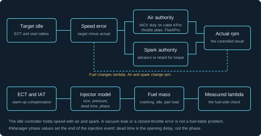
Idle speed is held by air and spark. Fuel is a separate model. This guide covers port-injected K20 and K24 engines on KPro and FlashPro. It covers the idle valve or throttle plate, the spark correction, injector size and dead time, and the cold-start phases that get mixed up.
- Idle speed is air plus spark. Fuel sets lambda. A fuel change cannot close an air leak.
- KPro cable throttle uses the idle air valve. FlashPro DBW uses the throttle plate.
- Injector size is flow at a pressure. Dead time is a separate voltage curve. The size scalar is not an idle trim.
- Crank, after-start, warm-up and hot restart are different phases. Log the transition, not only the steady idle.
- FlashPro blends cranking fuel into the main fuel over 10 to 30 seconds. It drops the after-start idle target at 20 to 60 seconds.
- No universal idle rpm, cold-start AFR or cranking multiplier is printed here. Read the target and the compensation from the calibration.
Full Custom: $249 $199 launch special. Most files in 3–5 business days after complete inputs; the outside limit is 7 business days.
Port-injected K20 and K24 only. The turbo Civic is the separate turbo section on the same Honda & Acura hub. Hondata or FuelTech hardware and credits are not included. How files are handled.
1. What this page covers
This guide covers port-injected K20 and K24 engines: cable-throttle KPro with an idle air valve, and DBW FlashPro with throttle-controlled idle air.
K20C, L15 and K24W direct-injection engines, B-series, D-series and s300 are outside this guide. Their fuel systems or software controls differ. FuelTech on a K has its own fuel model and guide.
| Route | Example applications | Idle air | Fuel settings |
|---|---|---|---|
| KPro, cable throttle | Manual-transmission 2002–2004 RSX K20A2/A3, 2002–2005 EP3 K20A3, cable-throttle K swap | Idle air valve and idle spark | KManager injector size, voltage compensation, fuel compensation |
| FlashPro, drive-by-wire | 2006–2011 Civic Si K20Z3, 2007–2014 TSX K24 | Throttle plate and idle spark | FlashProManager injector size, opening time, fuel pressure, compensation |
2. Classify the symptom before the table
Separate no-fire, catch-and-stall, warm-up and hot-restart complaints before choosing a table.
| Symptom | First read | Not the fix |
|---|---|---|
| Never fires | Sync, spark, fuel pressure, crank voltage and crank speed | Adding cranking fuel before those checks |
| Fires, then stalls in a few seconds | Immediate fuel blend and air capacity at the after-start target | A warm-up compensation change |
| Runs, then dies at one coolant temperature | Compensation at that temperature and the idle target transition | A global cranking trim |
| Hot restart only | Cranking pulse already too long, voltage, pressure and vapor lock | A cold-start table or a global cranking trim |
| Idle sags when the fan or lights come on | Voltage, lambda, trim and pulse at the loaded voltage | Raising the idle target |
| Idle hangs high or dips on release | Closed-throttle recognition, cable or stop, vacuum leak, valve or throttle capacity | Lowering the target or disabling the valve check |
| Surge at a steady warm idle | Air leak, TPS, idle valve or throttle, combustion | A different base calibration |
A log that begins after the engine is running cannot show cranking voltage or time to fire. A short warm-idle clip cannot show a cold-soak transition. Record from before the key to at least the point where the engine holds a steady idle.
If the complaint is a stall, the useful part of the log is the seconds before it, not the minutes after.
One reading is not a diagnosis. A lean wideband during a rough idle can come from a misfire or an exhaust leak. Oxygen that did not burn shows up as excess oxygen in the exhaust. Adding fuel to chase that reading makes the mixture richer without fixing the misfire.
Check pulse width, voltage, combustion and exhaust integrity before you move a fuel cell.
3. Injector data is flow, pressure, dead time and phase
An injector has a flow rating at a pressure, a dead time against voltage, a short-pulse behavior and a spray pattern. The software scalar covers the flow rating. It does not cover the other three. A larger entered flow shortens the pulse and leans the mixture.
A smaller entered flow lengthens the pulse and richens it. Either change lands on every load and on cranking, which is why a size change can look right at one load and wrong at idle.
More details
In KManager, changing the injector size compensates the fuel tables and the cranking fuel. It does not compensate the specific characteristics of the injector. The voltage compensation table is the dead time against battery voltage. In FlashProManager, the size change compensates main fuel, cranking fuel and closed loop.
The flow is nominally at 3 bar (43.5 psi). Where exposed, the stock/current fuel-pressure and injector-test-pressure fields compensate main fuel, cranking and closed loop. Do not also hand-scale those tables for the same pressure change.
Static flow can be estimated with the square root of the differential-pressure ratio. Take a 1000 cc/min injector rated at 3.0 bar as an arithmetic example. It moves 1080 cc/min at 3.5 bar. The arithmetic is 1000 × sqrt(3.5 / 3.0). That is arithmetic for the same injector, not a recommendation to raise pressure. The regulator reference matters. A manifold-referenced regulator holds differential pressure across the injector. A fixed-pressure system does not, so the same rail gauge number is not the same delivered flow.
| Battery voltage | Dead time |
|---|---|
| 6 V | 3.58 ms |
| 8 V | 2.36 ms |
| 10 V | 1.71 ms |
| 12 V | 1.22 ms |
| 16 V | 0.68 ms |
More details
The sheet rates this part at 1000 cc/min at 51 psi / 3.5 bar differential pressure. Its calculated flow at 3.0 bar is about 926 cc/min. If FlashPro exposes a current-injector test-pressure field, enter 1000 with 3.5 bar there and the actual operating pressure separately.
Alternatively, use the converted 926 figure with a 3.0 bar test pressure. Do not convert the flow and also leave 3.5 bar as its test pressure.
- Keep the other pressure settings unchanged. Entering 1000 instead of 926 against a 3.0 bar test pressure shortens the calculated delivery pulse by about 7.4%. The latency portion is separate. The DW dead-time row remains data at 3.5 bar; converting static flow does not convert latency to another pressure.
- For a simplified example, a 2 ms total command with 1 ms dead time leaves 1 ms of effective delivery. A 0.1 ms error is 10% of that window. A 10 ms total command leaves 9 ms; the same error is about 1.1%. Real short-pulse nonlinearity can depart from this subtraction model, so it cannot generate a missing injector curve.
- Confirm the part and the pressure. Record the injector part number, the rated pressure, the rail pressure and the regulator reference. Check for leaks, excessive pressure, a leaking injector and the wrong impedance or driver arrangement.
- Enter flow at the pressure the software uses. Then enter the latency curve for the exact part. Keep the data sheet revision and date with the calibration.
- Verify the measurement path. Check wideband scaling and warm-up. Confirm the ECU recognizes closed throttle using the channels for that application. Fix vacuum leaks before you change fuel.
- Warm the engine and log two steady points. Use idle and a steady part-throttle point. Compare the error at short and long pulse widths. A similar percentage at both points points to flow or pressure. An error that is large only at idle points to dead time, an air leak or combustion.
- Run the electrical-load test before you trim the size scalar for an idle-only error. The next section is the method.
- Make the smallest change and repeat. A dead-time change moves delivered fuel at every load. Recheck the fuel map after it, not only the idle.
Lowering the entered flow richens the idle and the whole load range, and it adds cranking fuel. Raising the entered flow leans all three. If the error is only at idle, the size scalar is the wrong tool in either direction.
A false size can hide a pressure or model fault and leave the rest of the calibration wrong.
More details
Injector phase is a separate setting. In KManager, the phase values determine the end of the injection event, when the injector closes. The same help gives the typical opening point at 400 to 500 crank degrees before TDC compression.
There are four phase values: idle, cruise low load, cruise medium load and wide-open. The first three are fixed; the wide-open values are indexed by rpm. A compensation table moves the event with the intake cam angle. Phase can change mixture formation.
It is not dead time, and it does not prove the spray is right.
4. Idle air and idle spark are the fast controls
Air determines the charge available; spark changes the torque it produces. Both help hold idle speed. Fueling must support stable combustion while those controls work.
More details
On a cable-throttle KPro car, the idle air valve meters air past the throttle plate. The hot target is a speed in rpm. The duty-cycle adjustment is a proportional trim on valve feedback. The KManager idle page says to increase the slider if the idle dips when you release the throttle.
Decrease it if the idle hangs high. That is after the mechanical checks, not before them. The same page notes that large injectors may need a richer hot-idle target to prevent lean misfires.
The Disable idle valve switch is an error-check switch. It does not seal the air path and it does not tune idle airflow. If the valve is removed and the passage is open, the engine gets air the ECU did not command. A block-off plate is the mechanical close. The software switch only stops the error check.
On a DBW FlashPro car, the throttle plate is the air actuator. There is no idle valve to clean or delete. Two coolant-indexed tables set the target: an after-start speed and a normal speed. The after-start target is used for 20 to 60 seconds, then the normal target takes over.
That is a target change, not a fuel blend. Do not tune it as if it were cranking fuel.
Idle spark moves to control torque. The FlashPro ignition page gives a normal idle range of −10 to +15 degrees. That movement can be normal when actual rpm follows the target. Persistent retard with overspeed still calls for an air-path check. That band is a FlashPro observation, not a KPro limit.
KManager's ignition-controlled idle uses target-versus-actual speed error tables, so use the table in the calibration you opened. Do not flatten the idle spark table to make the log look steady. Flattening it removes the fast correction in both directions.
The FlashPro help also has an Idle Torque Reserve paragraph. That paragraph is explicitly about Bosch ECUs. Its 0 degree average is not a K-series table target.
Swipe or use the arrow keys to read every label.
| Item | KPro cable throttle | FlashPro drive-by-wire |
|---|---|---|
| Idle air | Idle air valve | Throttle plate |
| Hot target | Idle Speed in rpm | Normal idle table indexed by coolant |
| After-start target | Read the start calibration | Separate after-start table, 20 to 60 seconds |
| Fast spark trim | Ignition controlled idle | Ignition controlled idle |
| Valve delete | Block-off plate plus disable check | Not applicable |
- Warm the engine fully and log the loop. Record target and actual rpm, TPS, MAP, idle valve duty or throttle command, spark, battery voltage and lambda.
- If the actual speed is high with the actuator at minimum, find the air. Check the throttle stop, cable tension, bypass passage, manifold and throttle gaskets, PCV and brake-booster plumbing. A lower target cannot remove uncommanded air.
- If the idle dips on return, confirm closed throttle first. Check closed-throttle recognition and that the valve or throttle has capacity. Then adjust the air trim. A dip is not automatically a target problem.
- Apply the loads the car actually has. Fan, headlights, demister, steering and A/C. Note whether the sag starts with the air actuator, a voltage change, a mixture error or spark correction at its limit.
- Settle the fuel before you chase the last few rpm. A misfire can make a wideband read lean. More fuel is not the answer to a misfire, and a steady mixture is the foundation for the air and spark check.
- Confirm hot restart and repeated deceleration to idle. A dyno idle at zero accessory load is one operating point, not the whole job.
Use the idle-learn sequence for the chassis and ECU, including its prerequisites and accessory settings. Confirm closed-throttle recognition, resolve relevant codes and check for air leaks before learning. A reset cannot repair an open throttle or leaking bypass.
5. Use electrical loads to check the voltage curve
A flow error tends to remain a similar percentage at different pulse widths. A dead-time error becomes more visible as delivery time gets shorter. Electrical loads can expose a voltage-related error, but alternator torque also changes the air needed to hold idle.
Compare settled rpm, MAP and pulse width before blaming the curve.
With valid closed-loop feedback, a trim that becomes more positive at lower voltage means the ECU is adding fuel. Too little entered dead time is one possible cause. A more negative trim means it is removing fuel, which can point to too much entered dead time.
Compare the change from the unloaded baseline, including learned correction. In open loop, compare measured lambda with the target instead.
| Observation | What it points to | Next check |
|---|---|---|
| Similar percentage error at idle and part throttle | Flow, pressure or size scalar | Part number, rated pressure, rail pressure and scalar |
| Large error at idle, small error at part throttle | Dead time or short-pulse behavior | The voltage curve at the voltage actually logged |
| Lean only with electrical load | Possible dead time too low at the loaded voltage | The dead-time cell for that voltage |
| Rich only with electrical load | Possible dead time too high at the loaded voltage | The same cell in the other direction |
| Lambda moves before the sensor is ready | Wideband readiness or scaling | Power, ground and conditioner warm-up |
| Lean with a misfire or exhaust leak | Oxygen that did not burn | Ignition and exhaust integrity first |
- Baseline warm, accessories off. Let voltage settle and record lambda, trim, pulse width, MAP, rpm and battery voltage.
- Add one load at a time. Fan, headlights, demister. Keep rpm and MAP as close as you can, then record the new voltage and the new lambda and trim.
- Repeat at a steady part-throttle point. Similar errors suggest flow or pressure. An error that shrinks at a longer pulse suggests dead time, but air leaks and short-pulse behavior can give similar symptoms.
- Correct the region actually used. The logged voltage may interpolate between two cells. Keep the curve smooth, change only the justified region and repeat both load states.
- Recheck idle and low-pulse cruise. A dead-time change that fixes idle also changes delivered fuel at cruise. Recheck the cruise trim.
- Recheck the fuel map. Dead time changes delivered fuel at every pulse width, so the map has to be checked after the latency change.
Do not blame latency if the fan also pulled voltage low enough to misfire, or if the wideband lost power during the test. Compare ECU battery voltage with measured injector supply voltage under load. A wiring drop needs a wiring repair, not a false latency curve.
One KPro owner with unstable voltage and misfire codes found a cracked battery terminal. That finding does not establish the final repair outcome.
6. Crank, catch, warm-up and hot restart are different phases
A start is a sequence, not a table. The ECU uses a cranking calculation, then blends to the main fuel calculation. It moves from an after-start idle target to the normal target, then applies warm-up compensation. Fuel blending follows elapsed time; running compensation follows temperature.
A change in one phase can worsen another.
| Phase | When | Fuel calculation | Air and spark | What to log |
|---|---|---|---|---|
| Crank | Key to about 600 rpm | Cranking table, cranking trim, air and coolant compensation | Fixed crank spark on the FlashPro strategy, typically 5 or 7 degrees BTDC; idle valve or throttle at its crank position | Voltage, crank rpm, pulse width, time to fire |
| Catch and after-start | After crossing about 600 rpm; first 10 to 30 seconds | Cranking fuel blends into the main table | After-start idle target, 20 to 60 seconds | Rpm, target, lambda, pulse, coolant |
| Warm-up | Minutes after the start | Coolant and air compensation on the main table | Normal coolant-indexed target; idle spark active | Coolant, target and actual rpm, trim |
| Hot restart | After a heat soak | Cranking fuel and vapor behavior | After-start or normal target, based on elapsed time and coolant | Voltage, pulse, time to fire |
Those thresholds and timers describe the documented FlashPro starting strategy. Read the KPro start settings from the actual KManager calibration.
- The fuel blend can finish while the after-start idle target remains active. Log target and actual rpm together. If the target steps down and actual speed follows, inspect the target transition before cranking fuel.
- The FlashPro starting-fuel page gives two cranking checks for that strategy. Battery voltage during crank should be about 10.5 V and should not drop below 9.2 V. Cranking speed should be over 150 rpm cold and about 200 rpm hot. Those are checks for that starting strategy, not proof that a starter or battery passes every electrical test on a swap.
- Begin from an overnight soak. Record ambient, coolant and intake-air temperature before the first key cycle. Record the fuel blend if it is known.
- Log before you crank. Capture minimum voltage, crank rpm, injector pulse, time to fire and time to a sustained idle. Note the coolant temperature at each event.
- If it never fires, stop adding fuel. Verify sync, spark, fuel pressure and the electrical cranking conditions first. A no-fire is not a cold-enrichment problem until those are sound.
- If it catches and stalls, inspect the immediate blend and air capacity. A start that catches then dies after several seconds is not the same as one that never fires.
- If it fails at one temperature, change that region. If it is hard at every cold temperature, change the cranking trim. A hot-only failure stays on the hot-restart checks: too much cranking fuel, voltage, pressure or vapor lock. Do not use a global change for a one-temperature fault or a hot start.
- Repeat a genuine cold soak and check the hot restart separately. A restart after a few seconds is not a second cold test. Valves are warmer and the fuel film has changed.
7. Warm-up trim and the delivered-fuel arithmetic
Warm-up fuel is a compensation against coolant temperature, not a second main map. KManager warns that both air- and water-temperature compensation edits may wait for an ignition cycle and several minutes of running. The water reading is buffered to reject fluctuations from air pockets.
Follow the application service procedure if using the service-connector shortcut for that water-temperature response. If you edit and retest immediately, you can conclude a table does nothing when it has not been applied yet.
- Negative compensation is not automatically wrong. Read the baseline and the delivered-fuel arithmetic. The FlashPro help gives the exact form for a negative cranking trim:
new trim = old trim + ((100 + old trim) × (change% / 100))
| Old trim | Delivered fuel | Add 10% delivered | New trim |
|---|---|---|---|
| −70% | 30% of base | 33% of base | −67% |
| −50% | 50% of base | 55% of base | −45% |
| −30% | 70% of base | 77% of base | −23% |
- At −70%, changing to −60% raises the remaining fuel factor from 30% to 40%. That adds 33.3% relative fuel, not 10%.
- For the documented FlashPro diagnostic, test +10%, +20% and +30% relative fuel changes from the starting baseline. If adding fuel worsens cranking, test −10%, −20% and −30% from that same baseline. These are separate tests, not successive multiplications. Use the formula above when the compensation already has a negative trim. Keep a temperature-specific fault in that region; do not use the global trim for a hot-only problem.
- Confirm the warm fuel map and the injector model first. A cold-start change on a bad warm calibration is a guess.
- Find the temperature where the fault occurs. Log coolant at the stall or the lean dip. Do not change a row you did not reach.
- Change only that region. Keep the rest of the compensation curve and the other starts intact.
- Cycle the key and run for several minutes before you judge. Both air- and water-temperature compensation edits can be delayed. An immediate retest can mislead you.
- Repeat a cold soak and a hot restart. A change that fixes the cold start can hurt the hot start, and the hot start is part of the same delivery.
- Do not use a global change for a one-temperature fault. It moves every start to fix one point.
8. Cams, big injectors and the target you can defend
A cam changes the air the engine wants at idle. More overlap lowers idle vacuum and makes the engine less tolerant of a lean mixture or a late spark. The target may need to be higher, and the idle air authority may need to be larger.
The cam target itself belongs to the VTC page. This page covers the idle air and the fuel that supports it.
- Raising the target can settle a cammed engine at idle. It cannot correct cam timing, a vacuum leak or a stuck valve. No stage table of idle speeds is printed here. Set a speed that holds stable with the actual cam, oil pressure, charging and accessory load. A target that only works with the lights off is not a finished idle.
- Big injectors make the short pulse the problem. A large injector at idle may be near its minimum pulse. Dead time, spray quality and cylinder-to-cylinder distribution matter more than the rated flow. A part with a clean spray and correct data can idle better than a larger part with a poor pattern. Do not enter a false size to chase an idle. That masks a pressure or model fault and changes the whole range.
| Complaint | First stage to check | What not to change |
|---|---|---|
| Idle lean or rich, part throttle acceptable | Dead time at the actual voltage, air leak, combustion | Size scalar |
| Whole range off by a similar percentage | Flow, pressure or size scalar | Idle target |
| Idle rich, load acceptable | Short pulse, dead time, spray | Load fuel map |
| Idle hangs high | Throttle stop, cable, air path | Fuel table |
| Idle dips with electrical load | Voltage, dead time, air capacity | Idle target |
| Cold start only | Cranking trim and coolant compensation | Warm fuel map |
- The K-series CAM channel help describes the intake cam as locked fully retarded for the first 10 seconds after startup. The VTC and VTEC guide covers that lock. The cam may therefore be at a different angle from its later warm-running command. Log the cam state during that window. Evaluate starting fuel there, then compare warm running after the cam follows its normal command.
- E85 changes cold-start behavior. Test at the actual ethanol content and the actual temperature. A fuel-flow correction alone does not prove the fuel vaporizes. The E85 guide covers blend measurement and separate start and running compensations.
9. Numbers used on this page
None of these is a target for your engine unless the row says so. The application column is part of the number.
| Quantity | Value | Applies to | What it is |
|---|---|---|---|
| Start threshold | About 600 rpm | FlashPro K-series starting strategy | The ECU treats the engine as running |
| Crank-to-main fuel blend | 10 to 30 seconds | FlashPro K-series | Fuel calculation transition |
| After-start idle | 20 to 60 seconds | FlashPro K-series | Target transition, separate from fuel blend |
| Cranking voltage | About 10.5 V, not below 9.2 V | FlashPro starting-fuel check | Test condition, not a charging specification |
| Cranking speed | Over 150 rpm cold, about 200 rpm hot | FlashPro starting-fuel check | Test condition for that strategy |
| Idle spark | −10 to +15 degrees | FlashPro ignition page | Normal range while the ECU controls torque |
| Cranking fuel test step | 10% steps, +30% to −30% | FlashPro starting-fuel diagnostic | Test procedure, not a target; stop at 30% either way |
| Negative trim example | −70% to −67% | Arithmetic for +10% delivered fuel | Documented worked example |
| DW 17U-08-1000-4 rated flow | 1000 cc/min at 51 psi / 3.5 bar | Exact part, sheet pressure | Not the 3 bar size-field entry unless the flow-test pressure is 3.5 bar |
| DW 17U-08-1000-4 dead time | 3.58/2.36/1.71/1.22/0.68 ms at 6/8/10/12/16 V | Exact part at 51 psi / 3.5 bar | Latency data for one characterized injector |
| Flow versus pressure, worked example | A 1000 cc/min part rated at 3.0 bar moves 1080 cc/min at 3.5 bar | Same injector, arithmetic | Square-root pressure correction |
| DW flow at 3.0 bar | About 926 cc/min | DW 17U-08-1000-4, arithmetic | 1000 at 3.5 bar corrected to 3.0 bar |
| Short-pulse illustration | 2 ms command, 1 ms dead time, 1 ms delivery | Engineering illustration | Explains why idle is sensitive to latency |
| Injector phase | 400 to 500 crank degrees before TDC typical opening | KManager K-series | Opening description only; not a value to type into the end-of-event field |
| Closed throttle | Calibrated closed TPS; DBW plate may remain open | Use the application's channel definitions | Closed-throttle recognition |
Questions
It idles fine cold and hunts as soon as it is warm. Where do I start?
Compare the start of the hunt with closed-loop entry, coolant temperature and the target-speed change. A cold fast idle can mask excess bypass air. One KPro4 K20A3 owner reported finding an idle-air assembly vacuum leak after seeing heavy idle retard.
Fixing the leak improved the reported idle timing; it did not establish that every remaining problem was solved.
If lambda starts cycling with fuel correction, check sensor validity and the warm base map before changing feedback settings. First resolve misfire codes, supply faults and exhaust leaks. A steady open-loop comparison can separate base-fuel error from feedback hunting when a tuner has a valid independent lambda measurement.
It still runs with the IAC passages covered. What does that mean?
On a cable-throttle car, air is entering through the blade or another bypass or leak. Isolating the IAC route does not identify which one. Check cable slack, blade seating, the throttle-body gasket and connected vacuum circuits. Do not apply the cable-throttle stop adjustment to DBW.
Reported repairs included correcting a blade held off its seat and restoring IAC operation. Another owner reported sealing a leaking throttle blade with a moly coating. Treat that as a reported repair, not a general coating instruction.
Follow the throttle-body maker's setting and coating procedure; do not turn the stop just to force a lower rpm.
Injector pulse is 17.22 ms at 758 rpm. Is that possible?
Yes. For one sequential injection per cylinder per four-stroke cycle, cycle time is 120000 / rpm milliseconds. At 758 rpm that is 158.3 ms, so 17.22 / 158.3 × 100 = 10.9% duty. That arithmetic checks plausibility, not whether the fuel quantity is correct.
This example assumes the log reports total injector duration. Confirm the channel units and injection mode before applying the calculation. A wideband pinned at its rich display limit cannot tell you how much richer the exhaust is. Check sensor readiness and the actual injector model before reducing fuel.
Which low-cam column should I change for idle?
Use the logged rpm, MAP and actual cam angle to locate the cells the ECU uses. Idle can interpolate across pressure and rpm cells, and across cam-angle tables. There is no fixed idle column for every K.
A vacuum leak or different cam moves the operating point, so repair the cause before reshaping those cells.
Why does it stumble and die after several minutes with no code?
Log coolant, target rpm, lambda and correction before the stall. If the target stays steady, check combustion and mechanical timing as well as compensation. One owner reported an exhaust cam one tooth out and a misleading crank-pulley TDC mark.
Verify mechanical timing against the engine's service references after head or chain work; a missing code does not clear it.
Why does the idle go rich when the headlights come on?
Compare settled fuel correction and ECU voltage before and after the load. Excess entered dead time at the lower voltage can richen the mixture. Check injector supply and grounds if their voltage differs from the ECU reading. The load test above separates this from actuator response and misfire.
Does disabling the IACV let me idle on timing alone?
The KManager switch disables the error check. It does not close the passage. Spark can vary torque only within the air available, so deleting the valve removes the ECU's adjustable bypass air. A sealed delete still needs enough air for cold starts and accessory loads; it is not a general surge repair.
Do I need a richer idle target with large injectors?
KManager provides an idle target lambda and notes that richer hot idle may prevent lean misfire with large injectors. First verify flow, pressure, dead time and combustion. A target change cannot restore control below an injector's usable pulse range. Choose the target from repeatable stable operation, including accessory loads.
Cold starts are fast but hot starts are slow. Should I add cranking fuel?
Check hot cranking voltage, speed and fuel pressure first. Excess cranking fuel and vapor lock are the documented fuel suspects for a hot-only failure. Keep the cold region unchanged while diagnosing it. The next overnight start is needed to validate any shared setting you alter.
Can I reuse RDX dead times from another ECU?
Confirm the exact injector, differential pressure, driver and the receiving software's definition of latency. One RDX owner reported different idle behavior on KPro and Haltech despite reusing the numbers. It did not establish a transferable correction curve. Use matching characterization rather than changing the entered flow to hide the difference.
What is the idle relearn after a throttle body change?
Use the chassis and ECU service procedure for the sequence, temperature, time and accessory settings. Verify closed-throttle recognition and repair leaks first. Learning around excess air can leave the same fault after the reset.
What is rotational idle?
The phrase describes a deliberately uneven idle made by a separate combustion-control strategy. The KManager and FlashPro idle pages do not document it as a selectable mode. Cycling the hot-idle target does not reproduce that strategy.
Send the calibration, the native log, the CSV export, the ECU or device identity, the injector part and pressure, the fuel and the hardware list. Tune Report is free. Honda Full Custom is open at $199 during the launch special ($249 regular).
Every file is compared against our 3 million+ tune values, with a final check-off by our lead tuner.
Tune Report is free if you want this file checked: open the Honda & Acura Tune Report.
A written review of your tune file and one log from your car.
Start a Honda & Acura Tune Report