
FuelTech FT550 and FT450 on a K-series: trigger and first log
Published
FuelTech FT550 and FT450 on a K-series need a crank signal, a cam phase signal, and a timing reference checked with a light. Injector data has to match the hardware. This guide covers the FT550, FT450 and FT600 on port-injected K20 and K24 engines, including the paired loom that is not sequential.
- Early K20/K24 hardware uses a 12+1 crank wheel, a 4+1 exhaust home wheel and a four-tooth intake feedback wheel.
- The 210 and 330 degree index entries are starting references. The timing light sets the working reference.
- A paired injector and coil loom is not sequential. Selecting sequential in software does not separate the splices.
- Set the ignition reference before you tune fuel. RPM alone does not prove phase.
- The single injector deadtime value and the battery voltage curve are two ways to enter the same latency. Do not use both.
- There is no Honda K.Count or K.Control strategy here. Do not read a FuelTech log as if it has one.
- No validated K base map or fuel cell range is printed here. The page gives the checks and the method.
Full Custom: $249 $199 launch special. Most files in 3–5 business days after complete inputs; the outside limit is 7 business days.
Port-injected K20 and K24 only. The turbo Civic is the separate turbo section on the same Honda & Acura hub. Hondata or FuelTech hardware and credits are not included. How files are handled.
1. The boundary: port-injected K20 and K24
- This page covers port-injected K20 and K24 engines on FuelTech FT450, FT550 and FT600. The trigger and cam details are for the early K hardware covered here. That hardware uses a 12+1 crank, a 4+1 exhaust home and four-tooth intake feedback. A later K24W, K20C or aftermarket wheel can differ, so inspect the wheel before you select a pattern.
- Commissioning establishes the signals, wiring and references needed before fuel tuning can begin.
| Build | Throttle | What has to match | First check |
|---|---|---|---|
| 2002–2004 RSX K20A2/A3; 2002–2005 US Civic Si EP3 K20A3 | Cable | FT450 or FT550/600; early 12+1 pattern | Crank connector pins and paired loom |
| 2005–2006 RSX K20Z1/A3 | Cable | Same early pattern; confirm the engine loom | Crank sensor connector and O2 route |
| Cable-throttle K20/K24 swap | Cable | FT450 with a matching K loom, or FT550/600 | Engine code, wheels and injector pairing |
| 2006–2011 Civic Si K20Z3 | Drive-by-wire | FT550 or FT600 for native throttle control | Pedal and throttle pair, cam feedback |
| 2012–2015 Civic Si K24Z7 | Drive-by-wire | FT550 or FT600; confirm the wheel | Wheel identity, throttle pair, cam feedback |
| 2013–2015 Accord K24W | Direct injection | Not this page | Rail and injection type |
- The 2013–2015 Accord K24W is direct injection and uses a different fuel system. K20C, L15, B/D and s300 work sit outside this page. KTuner is not covered. The rest of this page uses “early K” for the 12+1 hardware in the table, not for every K-series engine.
- The page does not print a base map or a fuel cell range. No complete FuelTech K calibration with a trigger scope, a timing-light record and a VVT zero is published here. This page gives the method and leaves the missing values open.
2. Three signals, three jobs
- The ECU has to answer two different questions. Where is the crank in its rotation, and which of the two revolutions is the engine on? The crank wheel answers the first. The exhaust cam home answers the second when sequential operation is used. The intake cam wheel answers a third question: where is the moving cam relative to its reference?
- On the early K20/K24 hardware covered here, the crank wheel is 12+1: twelve regular teeth plus one additional synchronization tooth. It is not a 12-1 missing-tooth wheel. The crank and both cam sensors are Hall-effect. The exhaust wheel is 4+1 and provides the home signal. The intake wheel has four equal teeth and provides moving-cam feedback. The four-stroke firing order is 1-3-4-2.
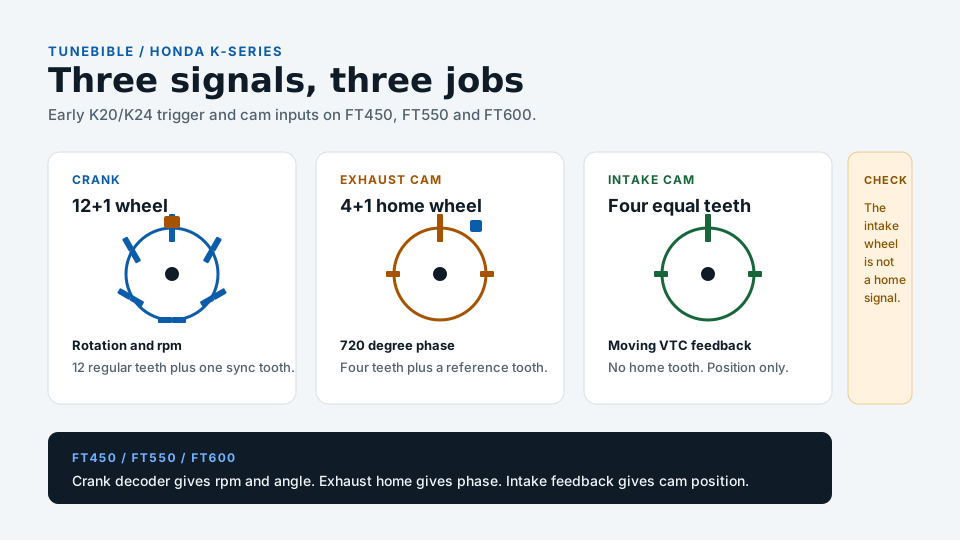
Swipe or use the arrow keys to read every label.
| Signal | Wheel | What it establishes | What it cannot establish |
|---|---|---|---|
| Crank | 12+1, Hall | Rotation angle and rpm | Which 720 degree revolution |
| Exhaust cam | 4+1 home, Hall | Phase and cylinder one reference | Continuous intake cam position |
| Intake cam | Four equal teeth, Hall | Moving VTC position | A home or phase reference |
| Stock coil | Integrated igniter | Logic signal from the ECU | Coil primary current is not supplied by the logic output |
- FuelTech’s RPM table lists 12+1 for a Honda Civic Si with an index of 210 or 330 degrees. Those are starting references, not two final settings. The correct reference depends on the wheel, the sensor edge and the decoder. A Haltech 311 degree figure belongs to a different decoder and does not transfer because the engine name matches. The timing light procedure in section 5 settles the working reference.
- The crank connector pin order differs across early K sensors. The K20 blue and K24 grey connectors carry the same three functions in a different order. Check the view before you repin: sensor pins, wire side and mating face are different drawings.
| Connector | Pin 1 | Pin 2 | Pin 3 |
|---|---|---|---|
| K20 blue | Signal | Signal ground | Switched 12 V |
| K24 grey | Switched 12 V | Signal | Ground |
The stock early K coil has an integrated igniter. The ECU drives a logic signal; the coil gets switched power and a head or engine ground. Coil primary current does not pass through the logic output.
A wrong coil or edge setting can damage the coil or the ECU, so verify the edge before the first crank.
An engine can show a steady cranking rpm and still have the wrong phase. A start that catches and dies can have a phase fault, a fuel fault or an uncontrolled air path. Check trigger diagnostics and output assignments alongside fuel pressure and idle airflow.
Cam sync and the timing light test the reference; the symptom alone does not identify the fault.
3. The FT450 K loom: sequential or paired
The FT450 has seven configurable inputs and ten outputs. It can run four independent injectors and coils, but pairing frees outputs for other functions. It is not enough for four independent injectors, four independent coils, VTC, VTEC, a pump and a fan at the same time.
Count the functions before you choose the loom.
| Function | Sequential outputs | Paired loom outputs |
|---|---|---|
| Injectors | 4 | 2 |
| Coils | 4 | 2 |
| VTC | 1 | 1 |
| VTEC | 1 | 1 |
| Fuel pump | 1 | 1 |
| Fan | 1 | 1 |
| Total | 12 | 8 |
A sequential four-injector, four-coil install with VTC and VTEC already uses all ten FT450 outputs before the pump and fan. That is why a paired loom exists. It frees outputs by sharing them and changes how the engine is configured.
| Function | Output or input | Pairing |
|---|---|---|
| Injectors 1 and 4 | Blue 1 | One output, two injectors |
| Injectors 2 and 3 | Blue 2 | One output, two injectors |
| Coils 1 and 4 | Grey 1 | One output, two coils |
| Coils 2 and 3 | Grey 2 | One output, two coils |
| VTC | Blue 5 | PWM output with built-in suppression on FT450 |
| VTEC | Blue 6 | On/off output |
| Fuel pump | Grey 4 | Relay control |
| Fan | Blue 3 | Relay control |
| Intake cam | White input 2 | VVT position feedback |
The pairing follows the firing order. Cylinders 1 and 4 are 360 degrees apart in the 720 degree cycle, and so are 2 and 3. One coil output can fire both in wasted spark. In Semi-sequential injection, each pair fires twice per 720 degree cycle.
The fuel model must match that event count.
- Selecting sequential mode does not unsplice the loom. With paired coils and sequential ignition, each coil output fires once per 720 degrees. The cylinder 360 degrees away loses its compression spark, and the engine runs on two cylinders. A paired coil loom needs wasted spark; a paired injector loom uses Semi-sequential injection for the paired strategy described here. Four independent coils and injectors need four outputs each and an ECU with the outputs to drive them.
- The 12+1 pattern can run wasted spark and Semi-sequential injection without cam sync. Sequential fuel or ignition needs the exhaust home reference. Intake feedback is still required for closed-loop VTC.
- The FT450 does not drive an electronic throttle. A cable-throttle K swap can use it. A drive-by-wire K20Z3 or K24Z7 needs FT550 or FT600 for native throttle control, or a cable conversion. The example FT450 loom also asks for high-impedance injectors and a separate charge loom. Those details still matter after the engine starts.
| Model | Inputs | Outputs | Throttle | VVT channels |
|---|---|---|---|---|
| FT450 | 7 | 10 | Cable | One intake, one exhaust |
| FT550 | 14 | 24 | Drive-by-wire | Up to two intake, two exhaust |
| FT600 | 20 in specification table | 32 | Drive-by-wire | Up to two intake, two exhaust |
- The FT600 specification table and buyer guide count 20 inputs; its product description counts 21. Budget from the configurable inputs in the connector diagram, rather than treating the headline count as spare sensor capacity. The FT450 and FT550 counts agree between the manual and the listing.
- Use the FuelTech FT450 K20-24 wiring diagram for the ECU and loom revision you have. Do not merge pin numbers from a third-party loom with the FuelTech drawing because both may use the same connector family. The functions may be the same and the pins may not be.
That sentence does not describe this loom. The pairing is wired into the loom, not selected in the mode menu. Match the mode to the loom, or rewire the loom to match the mode.
4. FT550 or FT450 base map and sensors before the first crank
FTManager 5.71 is the current PowerFT build on 4 November 2026. FT500 and FT500LITE compatibility stops at 4.91; use the documentation for the ECU and software version fitted. FuelTech Vision is the FT470 and FT700 family; its VE learning and direct-injection features do not transfer to FT450, FT550 or FT600.
- Write the identity sheet before you open the wizard. Record the engine code, head and cams. Add the crank and cam wheels, sensor connectors, injector part and flow, and coil part. Note the throttle type, MAP source, wideband controller, VTC and VTEC outputs, and fuel pressure. A “K24” label does not settle the trigger or the injector data.
- Set the engine limits. Maximum engine speed sets the last RPM point and the percentage-use display. Maximum boost sets the map extent, not the boost. For a turbo engine the manual suggests 10 psi above the maximum you will use; for a naturally aspirated K, 0.0 psi.
- Select the 12+1 crank pattern, Hall input and the edge that matches the sensor. Use a 210 or 330 degree index seed. Do not treat the seed as timing. The decoder and the timing light settle the reference.
- Set the injection and ignition mode to match the loom, not the other way around. Use wasted spark and Semi-sequential injection for the paired loom. Use sequential operation with cam sync when the outputs are independent. The mode is a description of the wiring.
- Enter the total injector flow for the bank. Four 80 lb/h injectors are 320 lb/h under the same pressure. Do not enter one injector’s flow as the bank total. Check the pressure the flow was rated at.
- Enter the injector deadtime from the injector data. The 2.9 manual uses 1.00 ms for high-impedance injectors and 0.60 ms for low-impedance injectors on a peak-and-hold driver. Those are defaults, not your injector’s specification.
- Enter dwell from the coil data. The wizard shows a 3.600 ms at 12.0 V example. That is an example, not a K coil specification. Coil type alone does not establish dwell; the wrong edge can damage the coil or the ECU.
- Calibrate TPS with the engine off. Check MAP against atmosphere and ECT and IAT against ambient. Associate the wideband before you generate the map, then generate the base map and print the connector view.
The generated map is a starting calibration, not a measured tune. It uses the compression category, fuel type, total flow, cam profile and deadtime you declared. If those inputs are wrong, the map is wrong in a way the O2 loop cannot repair.
| Input | What it changes | Where to read it |
|---|---|---|
| Compression category | Timing table shape | The engine build, not a generic K number |
| Fuel type | Fuel and start values | The fuel in the tank |
| Total injector flow | Fuel table scale | Injector data at the rated pressure |
| Cam profile | Vacuum rows | The cams in the engine |
| Deadtime | Low-load pulse | Injector data |
| Dwell | Coil charge time | Coil data |
| Maximum boost | Map extent | The boost target plus margin |
| Maximum engine speed | Last RPM point | The limiter, not a guess |
More details
The deadtime entry has a trap. In the current 5.71 help, the single Fuel injectors deadtime value is the 12 V latency at operating pressure. If you enter a full battery-voltage compensation curve, set that single value to 0.00 ms.
Otherwise the ECU adds the single value and the curve together. The engine runs rich at idle and the trim has to remove fuel that the table should not have added.
Do not crank if the sensor checks disagree or the loom pairing does not match the mode. Verify the selected wheel, edge and output assignments first. Check timing during a fuel-disabled crank where the light works, then confirm at steady fast idle after first start.
A file from another K is not a base map for this engine. It carries another engine’s injector flow, deadtime, trigger index, cam reference and fuel pressure. Generate from your hardware, then validate the sensors and the timing reference.
5. Set the timing reference with a light
The ignition calibration screen locks timing at 0 or 20 degrees at any rpm. The manual’s procedure holds a steady fast idle near 2,000 rpm and warns that rpm swings make the light wander. Do this before any fuel tuning or load run.
- Establish a trustworthy cylinder-one compression TDC mark. Some K pulleys have a mark you can use; verify it. If it is not trustworthy, establish true TDC mechanically and make a mark. With a dial indicator, bisect equal piston heights on either side of TDC; the piston dwell makes the apparent peak imprecise. A mark that is a degree off is a timing error at every rpm.
- Start the engine, open the ignition calibration function and lock the timing at 20 degrees. Hold a steady fast idle near 2,000 rpm.
- Point the light at the mark and adjust the compensation until the light shows the locked angle. Use 20 degrees on a correctly configured light, or 40 only after confirming that its display doubles. If the light reads 24 degrees when the screen is locked at 20, the error is 4 degrees. The manual specifies a −4 degree compensation for that example; remeasure after the change.
- Test the light before you trust a doubled reading. With the engine unloaded, change calibration compensation by 5 degrees, observe the light, then restore the original compensation. Keep the timing lock active during this check. If the light moves 10 degrees, the light is reading double. With doubling confirmed, a 46 degree display against the expected 40 needs a −3 degree compensation change, not −6.
- Check the reference at a second steady speed. A fixed offset stays fixed. A reading that drifts with rpm points to an edge, delay or trigger problem, not a number you can fix in the compensation box.
- Record the locked reference, the light reading and the final compensation. Then release the timing lock and confirm the screen and the light agree at the same steady speed.
The 210 and 330 degree entries in the RPM table are starting points. The manual says the values are only a start and the ignition calibration must always be performed. The same warning applies to a copied index from another engine. The timing light is the final check.
| Symptom | First check | What it means |
|---|---|---|
| Light reads 24 with 20 locked | Compensation and correction direction | A 4 degree offset |
| Light reads 46 with 20 locked | Light mode and the 5 degree test | If doubling is confirmed, the compensation change is −3 degrees, not −6 |
| Light moves with rpm | Trigger edge, sensor gap, shield | A signal problem, not a fixed offset |
| Light agrees at idle but not at speed | Second speed check, trigger diagnostics | Delay or edge problem |
| No stable reading | TDC mark, light mode, coil trigger | Fix the measurement before the map |
6. The fuel model is pulse time, not a Hondata table
In advanced 3D mode, Main fuel table holds pulse time against load and rpm. The load axis can be MAP or TPS. Basic 2D mode uses a load table plus RPM compensation. The table is not a Hondata VE table and it is not a self-learning VE model.
A display that looks like a volumetric-efficiency table or a duty table is a conversion of the pulse time, not a second fuel model.
More details
Pulse time has two parts: the deadtime and the fuel that actually flows. If the total pulse is 2.000 ms and the deadtime is 1.000 ms, the fuel part is 1.000 ms.
A 10 percent increase in delivered fuel adds 0.100 ms to the fuel part, so the new total is 2.100 ms. It is not 2.200 ms. At 8,000 rpm one 720 degree cycle is 15 ms, and a 12 ms event fills 80 percent of that window.
The event count and the injection mode still decide what that percentage means.
For a paired example, two 3 ms events per injector in that 15 ms cycle occupy 6 ms, or 40 percent duty. Two 12 ms events would need 24 ms in the same window. They cannot fit as separate events.
Confirm whether the displayed pulse is per event and use the logged duty for the configured mode.
The software separates Main fuel table, Overall fuel trim, Prime pulse, Engine start and Post-start enrichment. The start phases are not the warm running table; a prime that makes the engine fire can still be wrong hot.
O2 closed loop is a correction with enable conditions and authority limits, not a substitute for a correct base table.
| Control | What it does | First check |
|---|---|---|
| Main fuel table | Load table plus RPM compensation in basic mode; load/rpm table in advanced mode | Active load axis and injection mode |
| Overall fuel trim | Percentage change across the table | Whether the change is global or local |
| Prime pulse | Initial fuel when a crank tooth is first detected | Hot and cold restart |
| Engine start | Cranking fuel below the configured start threshold | Start pulse against ECT and voltage |
| Post-start enrichment | Fuel after the engine catches | Time and temperature |
| O2 closed loop | Feedback toward target | Sensor valid, enabled, authority |
| Battery voltage compensation | Latency change with voltage | Single deadtime value is zero if the curve is used |
| Acceleration enrichment | Fuel on throttle change | TPS rate and decay |
More details
The O2 association is a sequence, not a checkbox. In the current software, open Tools and CAN Network and associate the Nano as O2 General for a single sensor. Select the display scale. Enable O2 Closed Loop in Map Options and choose the sensor used for the average.
Then enable the associated sensors under Sensors and Calibration and CAN communication. Check that the ECU lambda agrees with the controller before the loop corrects anything. Compare lambda on both displays, or use the same AFR scale on both.
More details
A lambda that matches target while the trim is adding a large correction does not prove the base table is right. The feedback is supplying fuel the base is not delivering. Use a steady, valid correction to adjust the base once, then log again as feedback settles.
Do not apply the same correction twice.
The correct cell depends on injector flow, pressure, fuel, displacement, cam, rpm and load. Read the generated map, the lambda, the fuel pressure and the injector duty from your own file and log. A copied cell from another K does not describe this engine.
7. VTC and VTEC are separate functions
Honda calls the intake phasing VTC; FuelTech’s function is Variable camshaft (VVT). The 4.2 release added closed-loop VVT, and the older on/off function is now Variable camshaft (VTEC). VVT moves the intake cam continuously; VTEC switches the rocker to the high lobe.
A calibration that treats one as the other will not work.
| Model | Recommended VVT output | What to check |
|---|---|---|
| FT450 | Blue 5 has built-in suppression | Other blue outputs need the specified diode; grey outputs are not recommended |
| FT550 | Yellow output | Check the output can drive the solenoid; grey outputs are not recommended |
| FT600 | Yellow output | Check the output can drive the solenoid; grey outputs are not recommended |
The FT450 has no yellow outputs, which is why blue 5 is the one with the built-in suppression. If you use another blue output, add the diode the manual shows. A grey output is not recommended for VVT. This is a hardware limit, not a software preference.
- Establish the mechanical zero and the safe travel of the phaser before you command a target. Check chain indexing and oil pressure. The ECU does not know piston-to-valve clearance, and an aftermarket cam can turn a software target into contact.
- Keep the two cam signals in their own jobs. The exhaust 4+1 home goes to the cam sync input. The intake four-tooth feedback goes to the VVT position input. Do not use the intake wheel as the home reference.
- Set the sensor position angle and the target reference. FuelTech’s VVT target is relative to the configured sensor position and solenoid direction. The manual’s advance example has a sensor at 45 degrees and a 10 degree table value, which commands 55 degrees. That is an example of the arithmetic, not a Honda target.
- Keep VTEC off and command a small phase step with the engine warm. Log target, actual, duty, rpm, ECT and sync status. Confirm the cam moves in the direction you expect and returns.
- If the phase moves backward, stops at a fixed angle or oscillates, diagnose the reference and direction first. Check oil pressure, the solenoid and the sensor before you change a PID term. A stable loop can hold the wrong physical zero.
- Only after the small step repeats should you build the target table and the PID. Then enable VTEC and verify the mechanical switch separately. The output bit is a command, not proof that the rocker moved.
More details
Do not copy a Hondata cam-angle table into FuelTech; the numbers are referenced differently. Do not copy a 2JZ VVT PID set either. The manual’s 2JZ defaults are for that engine, not a Honda baseline.
The Honda frequency and PID values are not established here; read the actuator data and the actual response.
The table can command an angle the engine cannot safely reach. The mechanical stop, the valve relief and the cam card set the limit. The software only sets the request.
8. The first log has to answer a question
A log is useful when it contains the channels that can answer the question. The internal logger records up to 256 channels. The 2.9 manual’s sampling screen shows 25, 50, 100 and 200 Hz, and the tradeoff is memory.
Use faster rates for available sync-status and cam channels than for coolant temperature. These are processed values; a 200 Hz log is not a tooth waveform. Use trigger diagnostics or an oscilloscope for individual signal edges.
| Channel | Why it is there | What a bad trace looks like |
|---|---|---|
| Engine rpm | Crank decode and start | Zero, spikes or a drop at the same point |
| Crank sync or diagnostic status | Trigger quality | Sync loss, gap or tooth fault |
| Cam sync and cam angle | Phase | A phase that jumps or never appears |
| VVT target and actual | Cam control | Target moves, actual does not |
| VVT duty | Output and solenoid | Full duty with no movement |
| MAP | Load | A reading that does not change with throttle |
| TPS | Driver request | A stuck or uncalibrated range |
| Lambda | Mixture | A reading that disagrees with the controller |
| Fuel pressure and MAP | Injector differential pressure | Differential pressure falling below the configured reference |
| Injector pulse or duty | Fuel demand | Duty that is already high at low load |
| Ignition timing | Commanded spark | A trace that does not match the table |
| ECT and IAT | Enable conditions | Plausible but wrong ambient |
| Battery voltage | Latency and coils | A drop during crank |
| Knock input, if fitted | Noise or detonation | A channel that is not calibrated |
The current logger can save the map into the log file. Turn that on. It lets you match the log to the calibration later. Advanced diagnostics can record pulse edge, tooth count, timeout and noise information. Those channels are more useful than a single rpm trace when the engine will not sync.
- Set the log start and stop trigger. A manual button is fine for a first start. An rpm trigger is better for a road log. Confirm the memory policy before you record over a log you need.
- Choose basic or advanced logging. Basic uses one rate for every channel. Advanced lets you set the rate per channel. Use advanced when you need a fast trigger trace and a slow temperature trace in the same file.
- Download the log through FTManager’s Datalogger and Download path. Save the native .ftml file before you export anything. The native file is the record; the CSV is a copy.
- Export a CSV and read the first rows. Confirm the timestamp, channel names, units and sample rate. The exact 5.71 datalog export menu and header layout were not captured for this page. Do not invent a header name or a unit that the export does not show.
- Compare one value in the native log with the same value in the CSV at the same timestamp. If they differ, fix the export before you analyze the run.
- Keep the map, the native log, the CSV, the software build and the loom revision in one folder. The map and build let you trace commands back to their settings.
| Symptom | First channel | Next check |
|---|---|---|
| Cranks and shows rpm, will not start | Cam sync and phase | Cylinder assignment, timing reference, fuel and spark |
| Starts and dies after a few seconds | Sync, start fuel and rpm | Phase, start-to-run fuel transition and idle airflow |
| Runs on two cylinders | Coil output and firing order | Paired loom in sequential mode, or a wrong coil assignment |
| Backfire through the intake | Cam sync and timing reference | Phase, firing order, timing light |
| RPM drops out at one point | Crank sync diagnostics | Sensor gap, shield, edge, trigger wheel |
| Lean at idle, correct at load | Injector pulse and deadtime | Deadtime entry, pressure, vacuum leak |
| Lambda on target, trim at limit | Fuel trim and base pulse | Base table quantity and loop authority |
| VVT target moves, actual does not | VVT duty and oil pressure | Output driver, solenoid, oil supply, sensor |
| VTEC command on, no change | VTEC output and oil pressure | Solenoid, rocker, oil supply |
| Injector differential pressure falls with load | Fuel pressure, MAP and duty | Regulator reference, pump, relay, wiring, filter |
More details
The Honda logging guide covers export checks and channel interpretation. This page uses the channels that decide whether the FuelTech install is ready to tune.
9. Validate before you add load
Validation starts at warm idle and moves one step at a time. A first start that holds idle is not a tune. Check the sensors, the timing reference and the outputs before you add load.
| Stage | What to compare | Pass condition |
|---|---|---|
| Warm idle | Lambda, trim, MAP, TPS, ECT | Stable idle, plausible sensors, trim not at a limit |
| Part throttle | Lambda, pulse, MAP, timing | Mixture follows the table without a trim slope |
| VTC small step | Target, actual, duty, oil pressure | Cam moves in the right direction and returns |
| VTEC switch | Output state, rpm, torque response | Command agrees with pressure-switch feedback where fitted, mechanical operation and repeatable torque response |
| Hot restart | Start pulse, ECT, lambda | Starts without a pedal and holds idle |
| Fan and electrical load | Battery voltage, rpm, lambda | No stall, no voltage collapse, no mixture jump |
| Heat soak | Same channels after a soak | Behavior repeats, no new fault |
- Warm the engine and check the sensors before you touch the fuel table. A plausible but wrong ECT or MAP reading will make every correction wrong.
- Record a warm idle log and a part-throttle log. Compare lambda, trim and pulse. If the trim is adding fuel at idle, fix the base or the deadtime before you move to load.
- Run the VTC small step and the VTEC check separately. Do not change the cam target and the fuel table in the same run.
- Do the hot restart and the electrical load test. A car that starts cold and dies hot is not ready for a road log.
- Only then add load in steps. Keep the same route, the same fuel and the same channel set. Change one thing per run.
Send the map, the native log, the CSV, the software build, the loom revision and the sensor list when you want the file checked. Include the map so the log can be compared with the calibration.
Injector latency, coil dwell and VVT frequency/PID must match the actual hardware. Keep a scope capture, timing-light record and log with the calibration.
10. Numbers used on this page
A number on one row does not transfer to another engine or loom. The scope column is part of the number.
| Number | Applies to | How to read it |
|---|---|---|
| 12+1 | Early K20/K24 crank wheel covered here | Twelve regular teeth plus one sync tooth, not 12-1 |
| 4+1 | Early K20/K24 exhaust cam | Home and phase |
| 4 teeth | Early K20/K24 intake cam | Moving VVT feedback, not a home |
| 1-3-4-2 | Four-cylinder K20/K24 firing order | Pairs 1 and 4, 2 and 3 are 360 degrees apart |
| 210 / 330 degrees | FuelTech RPM table, 12+1 Honda Civic Si | Starting index, not final timing |
| 20 degrees | Ignition calibration lock, FT450/550/600 | Timing-light reference |
| 24 vs 20 degrees | Calibration example | 4 degree offset; correct and remeasure |
| 46 vs 40 degrees | Wasted-spark light example | 3 degree correction, not 6 |
| 7 / 10 | FT450 inputs / outputs | Model specification, not a K requirement |
| 14 / 24 | FT550 inputs / outputs | Model specification |
| 5.71 | FTManager current build, 4 November 2026 | FT500/FT500LITE stop at 4.91 |
| 4.2 | PowerFT release | Added closed-loop VVT; old on/off function renamed VTEC |
| 256 channels | Internal logger | Memory and rate tradeoff |
| 25 / 50 / 100 / 200 Hz | Manual 2.9 sampling screen | Not every rate on every channel |
| 15 ms at 8,000 rpm | One 720 degree cycle | 12 ms is 80 percent of the window |
| 2.000 to 2.100 ms | 10 percent fuel change with 1.000 ms deadtime | Add to the fuel part, not the total pulse |
| 1.00 / 0.60 ms | Manual 2.9 deadtime defaults | High impedance / low impedance with peak and hold |
| 0.00 ms | 5.71 single deadtime with a voltage curve | Do not double-compensate |
| 320 lb/h | Four 80 lb/h injectors | Total bank flow at the same pressure |
| 3.600 ms at 12.0 V | Wizard dwell example | Not a K coil specification |
| 10 psi | Manual margin above maximum boost for map extent | Not a boost target |
| 45 + 10 degrees | VVT manual example | Target relative to sensor position, not a Honda target |
| 1 and 4 / 2 and 3 | Example FT450 K loom | That loom, not every loom |
Questions
Can I download a FuelTech base map for a K?
Not as a shortcut. A base map is generated from declared hardware: engine size, compression, fuel, total injector flow, cam profile, deadtime and trigger pattern. A file from another K carries another engine’s injector flow, pressure, trigger index and cam reference.
Generate the map from your hardware, print the connector view, and validate the sensors and the timing reference. If someone offers you a file, ask for the exact engine, injectors, pressure, wheel, loom revision and software build. Without that list, the file is not a base map for your car.
Is the FT450 K loom sequential?
The published FT450 K loom pairs injectors 1 and 4 on blue 1 and injectors 2 and 3 on blue 2. It pairs coils 1 and 4 on grey 1 and coils 2 and 3 on grey 2. That is paired operation, not four independent channels.
Selecting sequential mode in software does not separate the splices. A paired coil loom needs wasted spark. If you want four independent coils and injectors, use a different loom and an ECU with enough outputs. Read the pinout for the loom you actually have.
How do I set TDC if the K pulley mark is not trustworthy?
Establish true cylinder-one TDC mechanically and mark it. With a dial indicator, bisect equal piston heights around TDC rather than relying on the apparent peak. Then start the engine, lock the ignition calibration at 20 degrees and hold a steady fast idle near 2,000 rpm.
Adjust compensation until the verified light reads the locked angle. If the light reads 24, the error is 4 degrees. Check the light’s doubling behavior with the 5 degree test before you halve a correction. Confirm the reference at a second speed.
A mark that moves with rpm is a trigger problem, not a mark problem.
Which index is right, 210 or 330 degrees?
Either can be a starting reference for the 12+1 Honda Civic Si pattern. Neither is a final setting. The correct reference depends on the wheel, the sensor edge and the decoder.
A Haltech 311 degree setting is for a different decoder and does not transfer because the engine name is the same. Use the FuelTech index as a seed, verify timing during a fuel-disabled crank where possible, then confirm at fast idle.
If the engine will not start on either seed, check the pattern and the edge. Check the sensor supply and the cam sync before you try another number.
Does the FT450 support VTC?
Yes, with closed-loop VVT from the 4.2 release. The FT450 controls one intake and one exhaust cam. Blue 5 has built-in suppression for the VVT solenoid; other blue outputs need the specified diode, and grey outputs are not recommended.
The ECU still needs the intake cam feedback, a valid sensor reference and oil pressure. The FT450 does not drive an electronic throttle, so a drive-by-wire K needs FT550 or FT600. VTC support is not the same as a wired and validated phaser.
Can I copy Hondata cam targets into FuelTech?
No. FuelTech’s VVT target is relative to the configured sensor position, not a Hondata crank-degree table. In the manual’s advance example, a sensor at 45 degrees and a 10 degree value command 55 degrees. That shows the arithmetic, not a Honda target.
Establish the physical zero, the direction and the safe travel first. Then command a small step and watch target and actual. The mechanical stop and valve clearance set the limit. A plausible screen value does not prove the cam is at that angle.
Why does it show RPM, fire briefly and die?
RPM alone does not validate the trigger pattern or phase. Read the diagnostic errors during cranking and during the brief run. Check output assignments, timing, injector data and fuel pressure. Also log the transition from Engine start to normal fueling.
The start threshold is configurable; 400 rpm is the manual’s stated behavior, not a fixed limit for every file.
One stock K20Z1/FT550 case had black plugs, intermittent trigger errors and an uncontrolled IAC on a relocation plate. Raising fuel pressure did not keep it running. No confirmed repair was reported. Test the air bypass and injector data rather than repeating the pressure increase.
What should I check for gap, missed-tooth and cam-sync noise errors?
Save the map, diagnostic capture and cranking log before changing settings. Check the selected wheel against the actual wheel, then sensor power and ground during cranking. Inspect connector pin order, shielding and edge selection. Capture crank and exhaust-home signals together to check their relationship.
A smooth dashboard RPM trace can hide individual decode errors. Do not tune around active sync faults with extra fuel or a different index guessed from a video.
Do I need to cut the factory wheel to 12-1?
No. The documented early wheel has a supported 12+1 pattern. Cutting a tooth changes the hardware and invalidates the original pattern and reference. Identify an already modified wheel before selecting its decoder. A video’s 12-1 settings and an unmodified 12+1 setup describe different hardware; neither supplies your final timing calibration.
Why does idle race when I use ignition-only idle control?
Ignition control changes torque but does not close an air passage. A disconnected idle-air valve can remain open. Check the throttle stop, vacuum ports and IAC bypass. If the valve will not be controlled, provide a correctly sealed bypass arrangement and a deliberate idle-air setting. Recalibrate TPS after changing the stop.
Blocking the IAC was suggested in the K20Z1 case; no follow-up established it as the completed repair.
Why does VTC do nothing and then jump to 50 degrees?
Separate a bad angle reading from uncontrolled cam motion. With control disabled, confirm the mechanical rest position, sensor reference and repeatable feedback. Then check activation conditions, logged duty and voltage across the solenoid. Blue 5 is a low-side driver: the other solenoid terminal needs switched supply in the documented circuit.
One FT450 owner restored lost cam feedback after revisiting sensor settings, then saw PWM activity but still reported overshoot. That was a partial recovery, not a completed VTC fix. Swapping the two solenoid wires did not solve it. Verify the supply and driver arrangement, zero, direction and safe travel before changing PID.
The ECU model or a 50 degree gear alone does not identify the cause.
Does FuelTech give me Honda knock control?
No. There is no established Honda K.Count or K.Control strategy in this installation. A generic input can accept a conditioned signal from an external knock monitor, if that monitor is calibrated. The ECU still does not manage the Honda per-cylinder knock retard.
Do not read a FuelTech log as if it has a KPro knock channel. Use a calibrated listening method, a verified timing reference and a controlled load step. No universal timing number is printed here, because the engine and the fuel set the limit.
Can I use the stock Honda O2 sensor?
Not as a direct wideband input. A stock wideband sensor needs its matching conditioner; narrowband Honda sensors cannot report mixture across the wideband range. FT450, FT550 and FT600 need an external wideband controller, such as a WB-O2 Nano, and a valid CAN or analog association.
The sensor’s presence in the exhaust does not give FuelTech the Honda conditioner. Fit the controller the ECU supports, associate it, and compare the ECU lambda with the controller before closed loop is enabled. Sensor placement and exhaust leaks still matter.
Why does it run on two cylinders after I selected sequential?
The loom is probably paired. With coils 1 and 4 on one output, a sequential setting fires that output once per 720 degrees. Cylinder 1 gets a compression spark and cylinder 4 gets an exhaust spark.
On the next cycle the output fires at cylinder 1 again, so cylinder 4 never gets a compression spark. Use the wasted-spark mode for a paired coil loom, or rewire to four independent coil outputs. Check the firing order and the coil assignment at the same time.
A wrong pair can look like a failed coil.
Send the map, the native log, the CSV, the software build, the loom revision and the sensor list for a free Tune Report. Honda Full Custom is open at $199 during the launch special ($249 regular).
Every file is compared against our 3 million+ tune values, with a final check-off by our lead tuner.
Tune Report is free if you want this file checked: open the Honda & Acura Tune Report.
A written review of your tune file and one log from your car.
Start a Honda & Acura Tune Report