
Hondata KPro and FlashPro fuel tables on a K-series
Published
A K-series fuel correction is only valid in the model the ECU is using. KPro has six cam tables per VTEC state and blends between neighboring angles. FlashPro may be running AFM, MAP or a hybrid of both. Name the model and the active table before you change a number.
A fuel table edit can look correct in the software and change nothing in the engine. Three causes are common. The calibration is AFM-based and the MAP tables are unused. The cam angle is not on the table you edited. A closed-loop trim already supplies the fuel you are about to add.
Each cause is visible in the calibration or the log before the next edit.
- Name the active fuel model first: AFM, MAP or hybrid, and the cam angle.
- Set injector flow, pressure and latency before you change the fuel table.
- Correct from a steady-state sample; do not stack a global trim on a table correction.
Full Custom: $249 $199 launch special. Most files in 3–5 business days after complete inputs; the outside limit is 7 business days.
Port-injected K20 and K24 only. The turbo Civic is the separate turbo section on the same Honda & Acura hub. Hondata or FuelTech hardware and credits are not included. How files are handled.
1. The boundary: port-injected K20 and K24
This procedure covers the port-injected engines below. The year gets you close. The ECU, the calibration and the installed hardware settle the rest.
| Vehicle or swap | Engine | Control route |
|---|---|---|
| 2002–2004 RSX | K20A2, K20A3 | KPro in an eligible 2002–2004 ECU |
| 2002–2005 EP3 Civic | K20A3 | KPro in its PNF ECU |
| 2005–2006 RSX | K20Z1, K20A3 | KPro on a modified 2002–2004 ECU, matching adapter and earlier primary oxygen sensor |
| 2006–2011 Civic Si | K20Z3 | FlashPro, native drive-by-wire |
| 2004–2006 TSX | K24A2 | FlashPro conversion with a 2007–2008 ECU and CAN adapter; VIN and immobilizer matching required |
| 2007–2014 TSX four-cylinder | K24 | FlashPro, supported ECU list |
| 2012–2015 Civic Si; 2013–2015 ILX 2.4 manual | K24Z7 | FlashPro |
| Cable-throttle K swap | K20 or K24 | KPro in an eligible ECU, or FuelTech |
The 2005–2006 RSX conversion uses a 2002–2004 RSX or 2002–2005 Civic Si primary oxygen sensor. The original ECU cannot accept KPro. An adapter alone does not convert an unmodified earlier ECU.
The 2013–2015 Accord K24W is a direct-injection engine and does not use the port-injector model on this page. No flow, dead-time or VE recipe here applies to it. K20C, L15, B/D and s300 work sit outside this wave, and KTuner is not covered.
FuelTech on a K has its own fuel model and its own page.
2. Name the active fuel model first
KPro calculates fuel from engine speed and manifold pressure. The fuel table is split by VTEC state and then by intake cam angle. The table window shows low-speed and high-speed fuel tables, each with six cam-angle tables at 0, 10, 20, 30, 40 and 50 degrees.
The ECU interpolates between breakpoints, so the active value is a blend unless the engine sits exactly on one.
- The number in a KPro fuel cell is the calibration's fuel value. Do not read it as a VE percentage that can be compared with another file. Apply a percentage change to the selected cells, then use the log to see whether that percentage moved lambda toward the target. The same number in a different calibration does not describe the same mixture.
- FlashPro can run an AFM calibration, a MAP calibration or a hybrid of the two. Fuel Table Type in the calibration says which. AFM systems calculate injector duration from the mass of air per cylinder and do not use the MAP fuel tables. MAP systems use volumetric efficiency tables indexed by engine speed and manifold pressure. On a hybrid, the ECU uses AFM below the Minimum pressure for speed/density and MAP at or above that pressure.
- That threshold is a load boundary, not a tuning preference. Above the switch, an AFM Flow edit does not control fuel. Below the switch, a MAP fuel cell does not control fuel. Check the type and the threshold before you decide a table had no effect.
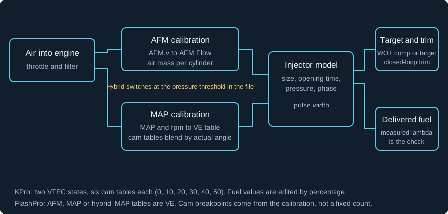
Swipe or use the arrow keys to read every label.
- At 24 degrees actual cam angle, KPro blends the 20 and 30 degree tables. Editing only one changes part of the delivered fuel. Match both VTEC state and actual cam angle to the sample.
- FlashPro's part-throttle procedure gives two five-angle examples: 0, 10, 20, 30, 40 degrees or 0, 15, 30, 40, 50 degrees. Read the breakpoints from the calibration instead of assuming KPro's six-table layout.
| Software | Table | What the value means | First check |
|---|---|---|---|
| KPro | Low-speed and high-speed Fuel | Calibration fuel value at rpm, load and cam angle | Actual cam angle and VTEC state in the log |
| FlashPro, MAP | Fuel tables (MAP based systems) | Volumetric efficiency in speed density | Fuel Table Type, cam breakpoints and MAP sensor scaling |
| FlashPro, AFM | AFM Fuel and AFM Flow | Air mass to injector duration, with a voltage-to-flow transfer | AFM.v against S.TRIM, closed loop active |
| FlashPro, either | WOT lambda adjustment | Enrichment on a base quantity that assumes stoichiometry | The 0.85 lambda warning and the active closed-loop state |
3. How one injection event is calculated
The ECU estimates air and selects or blends a fuel table. It calculates a base injector duration, applies the injector model and then applies the target or feedback correction. A mistake at any stage looks like a fuel-table error at the others.
More details
On KPro, the factory base tables are calibrated to deliver lambda 1 before enrichment, nominally 14.7:1 on a gasoline scale. Full-load enrichment comes from WOT compensation tables, which add fuel on top of a base quantity that assumes stoichiometry.
The compensation tables are not target lambda tables, even when their values are shown in lambda or AFR.
KPro4 adds a separate path. Closed Loop Advanced offers no WOT compensation, a fixed lambda 0.85, WOT compensation tables, or true target lambda tables. In target mode, changing the target changes fuel in both open and closed loop, and the WOT compensation tables are replaced.
The fixed 0.85 option applies compensation in open loop; it is not a target to copy.
The ECT target calculation is a third path. Target Lambda ECT Low and Target Lambda ECT High are read at load points near 32 kPa and 82 kPa. The ECU interpolates them by load, then compares the result with Target Lambda Limit. The richer of the interpolated value and the limit wins.
These tables set the closed-loop target under their own conditions. They are not the full-load target table.
FlashPro's WOT lambda adjustment has a documented limit. A value leaner than 0.85 lambda, or 12.50 on the gasoline scale, keeps that strategy in closed loop. That is a warning about the table and the software.
It does not establish that a naturally aspirated K cannot make peak torque leaner than 0.90 lambda.
In KManager, the injector size setting rescales the fuel tables and cranking fuel, and the help says that does not cover the injector's specific characteristics. In FlashPro, changing injector size compensates the main fuel tables, cranking fuel and closed-loop operation. Do not apply the injector-size ratio again as a table trim.
Injector opening time adds the electrical delay before flow, and it varies with battery voltage. Fuel pressure settings correct for the difference between the flow-test pressure and the pressure on the car. Injector phase sets when the injector event ends, not how long it lasts.
Air temperature, coolant temperature and cranking compensation then modify the result. FlashPro's fuel-parameters help says positive values add fuel and negative values reduce it on the intake-air, cranking-air, coolant and cranking-coolant tables.
KManager describes a correction factor: a higher factor adds fuel, a lower factor removes it, and it does not ask for a negative number. In KManager, the air and coolant compensation changes may wait until the ignition is switched off and the engine is restarted.
The changes apply after the engine has run for several minutes. Do not use a compensation table to cover a mechanical fault or a wrong injector setting.
4. Read the log before you change a cell
A fuel sample is only useful when the operating state is stable. Record rpm, manifold pressure, throttle, actual cam angle, cam target and VTEC state. Add lambda, short-term trim, long-term trim, injector pulse width and battery voltage. Include intake air temperature and coolant temperature. Add fuel pressure if the car has a sensor for it. The Honda logging guide covers the export and channel definitions.
- A useful trace holds rpm and load steady through the cell and holds the cam angle steady. Battery voltage stays stable, and the closed-loop state is known. Lambda should sit near the target without the trim swinging. A bad trace includes throttle tip-in or tip-out, injector cut, start-up, sensor warm-up, misfire, a pressure drop, or a moving cam angle. Those samples describe a transition, not a steady cell.
- During confirmed overrun fuel cut, lambda near 2.0 describes oxygen in the exhaust, not a mixture error. Confirm zero injector pulse before excluding the sample. Do not add fuel to correct a sample taken during fuel cut.
- Lambda on target with +15% short-term trim means feedback is adding fuel. Establish the injector, pressure and sensor model before correcting the base table. Apply a trim-aware overlay once; adding STFT again would count the same correction twice.
| Symptom | First channel | What it does not prove |
|---|---|---|
| MAP fuel edit has no effect | Fuel Table Type and Minimum pressure for speed/density | That the table is broken or the write failed |
| Correction works in one pull, not the next | Actual cam angle at the sample | That the cell value is wrong everywhere |
| Lambda is flat but trim is large | Short-term and long-term trim beside lambda | That the base fuel table is correct |
| Idle is lean after an injector swap | Opening time, battery voltage and pressure | That the advertised flow number is wrong |
| Error appears only at the VTEC switch | Actual cam, VTEC state, lambda and injector pulse | That a one-cell enrichment spike is the fix |
| Error follows a temperature change | IAT or ECT compensation and the logged temperature | That the main fuel table needs a global change |
5. Set injector and pressure data before the table
The injector model has to match the hardware before a fuel correction means anything. A table tuned around wrong dead time will hold a mixture at one voltage and drift at another. A table tuned around the wrong test pressure will be wrong as soon as the rail pressure changes.
- Record the exact injector. Part number, flow, test fluid, test pressure, impedance and the latency points by voltage. Stop if the only number you have is a seller's nominal flow.
- Establish the pressure reference. With an adjustable manifold-referenced regulator, set base pressure using its specified pump-running procedure, with no vacuum or boost on the reference port. A stock returnless system has no regulator to adjust; measure what it does rather than treating a swap-guide pressure as its specification.
- Enter flow and latency in the right fields. In FlashPro, the current pressure and the injector test pressure are separate inputs. Entering both and then adding a global trim for the same pressure difference applies the correction twice.
- Check the sensors that judge the result. Confirm MAP at key-on and the oxygen sensor scaling before you calculate a fuel error. A wrong pressure or oxygen reading makes a correct table look wrong.
- Warm the engine and log idle and steady cruise. Include battery voltage and both trims. An error at every load suggests model or global scaling. An idle-only error that tracks voltage suggests opening time, an air leak or injector nonlinearity.
- Load the electrical system at a steady rpm and load. Compare lambda and trim with the alternator charging and with accessories on. Only then move to the spatial fuel table.
Keep injector rating pressure separate from rail pressure. FlashPro has stock/current pressure and injector test-pressure inputs. KManager's size adjustment does not characterize pressure-dependent latency or short-pulse behavior; retain the pressure assumptions supplied with the calibration.
- Aftermarket data has to travel with its rating pressure. The ID1050-XDS is rated 1065 cc/min at 3.0 bar with gasoline at 52 degrees Celsius. The DeatschWerks 17U-08-1000-4 is a 1000 cc/min injector. Its Hondata-format latency data is published at 51 psi, or 3.5 bar, so do not treat the whole sheet as a 3 bar characterization.
- Pressure changes flow by the square root of the differential-pressure ratio: Q2 equals Q1 times the square root of dP2 divided by dP1. A 1000 cc/min injector at 3.0 bar becomes about 1080 cc/min at 3.5 bar. That assumes incompressible flow and an otherwise unchanged model. It is arithmetic, not a recommendation to raise pressure.
- Differential pressure is rail pressure minus manifold pressure, with both on the same reference. For example, a fixed 50 psi gauge rail at 10 psi boost gives 40 psi across the injector. Flow relative to 50 psi falls to the square root of 40/50, or 89.4%. A working 1:1 boost-referenced regulator instead raises rail pressure with boost to preserve the differential.
- Displacement is a sanity check, not a correction. A 2354 cc K24 is 1.178 times a 1998 cc K20, so the same breathing would need 17.8% more fuel. The head, cams, manifold and rpm change the shape as well as the scale. Do not multiply a K20 table by 1.178 and call it a K24 calibration.
If a new injector idles lean, the opening time, the pressure or the voltage compensation is the first suspect. Lowering the entered injector size until idle looks right hides the error at every other load. Keep the real flow number and correct the latency data.
6. Tune KPro cam-angle tables at a fixed angle
Fix the cam at one safe angle, tune that table, then repeat for the angles and VTEC states the engine uses.
- Save the file and record the composite cam targets. You will restore them after the fuel work. Keep the as-found file untouched and work from a copy.
- Establish that the valvetrain has clearance for the angles you will command. A software angle is not a clearance measurement. The VTC and VTEC guide covers the mechanical check and the cam target tables.
- Start on the low cam at one angle. Lock the low-speed cam table to that angle. Log actual cam, target, rpm, MAP, lambda, trims, injector pulse, battery voltage, IAT, ECT and VTEC state.
- Collect steady samples across the region you intend to change. Exclude tip-in, tip-out, fuel cut, start-up, warm-up, misfire and any sample where the cam is still moving.
- Choose one correction method. A zero-trim open-loop test calculates measured lambda divided by target lambda. A trim-aware overlay uses the trims and lambda together. Do not mix the two methods inside one correction and then attribute the result to the table.
- Edit the table at the locked angle. Unselect Edit All Tables for an angle-specific correction. If actual cam is between breakpoints, both neighboring tables contribute; collect a settled fixed-angle sample before isolating either one.
- Re-log the same region. Check the cell you changed and the neighbors. Repeat at the safe angles used on each VTEC lobe. Restore the composite targets, save and upload the tuned file, then check the transitions.
KManager's Fuel Adjustment overlay is calculated from the ratio of actual lambda to target lambda. The software notes that the estimate depends on many factors and is intended to show the regions that need work. Treat the overlay as a direction, then verify the result in the next log.
- Ctrl+J opens Adjust Selected Values for the selected cells. Fuel edits applied across cam tables are always percentage changes, even when the edit in the current table is an absolute value. That behavior matters when Edit All Tables is selected.
- Edit All Tables changes all related cam-angle tables together. It is useful when the tables are similar and the correction is a broad shape change. It is wrong when the error is local to one angle, because it moves five tables you did not log. Check the box state before every apply, not after.
- For a simplified blend example, let matching 20-degree and 30-degree cells both contain 100 calibration units. At 24 degrees, their weights are 60% and 40%. Adding 10% only to the 30-degree cell gives 0.6 × 100 + 0.4 × 110 = 104, a 4% blended increase. These are invented values to show interpolation, not cells to enter. Re-log with the composite cam targets restored.
- Stop the session if a change produces a lean condition you cannot explain, a new misfire, or a fuel pressure drop. A fuel table is not the place to diagnose a failing pump or a blocked filter.
7. Choose the FlashPro MAP or AFM procedure
Use the procedure for the active model: MAP edits volumetric efficiency; AFM edits the voltage-to-flow transfer. A hybrid needs each region checked separately.
MAP calibration
The part-throttle MAP procedure can run in closed loop. The software reads the fuel trims and the measured lambda to calculate the fuel change, so forcing open loop is not a prerequisite. That is a difference from the older KManager instruction to zero the short-term trim limits.
- Confirm Fuel Table Type and the cam breakpoints. Write down the angles the calibration uses. Do not assume the KPro 0-to-50 set.
- Select the low-speed cam fuel tables and confirm the cam angle. Unselect All so the percentage does not land on every cam table. Lock the cam to the first angle and save the test calibration under a different name. Keep the original cam-angle table for restoration.
- Record a light-throttle pull in first and second. Hold a steady throttle so load stays consistent as rpm rises. Start near 1000 rpm and stop about 1000 rpm past the VTEC point. The first and last rows often carry tip-in and release error.
- Show Fuel Change with Shift+F3. The overlay uses lambda, the target and fuel trims to suggest a percentage. Look for a pattern across a column or a block of rows.
- Apply the pattern, not single cells. Keep the 2D load lines smooth and evenly spaced. If the suggested change would make a bump, apply less to a larger area.
- Repeat for the same angle until the suggested change is close to zero. Then lock the next safe angle and repeat. Finally, copy only the original low-speed cam-angle table into the tuned file. Save and upload that tuned file; uploading the whole original would discard the fuel work.
The documented method can take three or four cycles per angle. Recheck the 2D shape after every correction.
AFM calibration
The AFM procedure starts from stock injectors, stock AFM flow values and stock WOT compensation values. If those are not the baseline, the trim pattern is describing the previous changes as well as the sensor transfer.
- Warm the engine and record 5 to 10 minutes of varied driving. Keep the log in closed loop and include steady cruise, light acceleration and some deceleration.
- Open the XY graph from Advanced Graphs. Put AFM.v on the X axis and S.TRIM on the Y axis. Show the mean, select closed loop and exclude open loop.
- Read the trend by voltage band. A band that consistently pulls fuel is reporting more air than the engine is using. A band that consistently adds fuel is reporting less.
- Change a small number of bands at a time. The software's own procedure limits this to two or three changes, then a re-test. Keep a copy of the original transfer.
- Re-log and check the same bands. The aim in the procedure is trims within 1%. If a band gives inconsistent trims on repeat tests, check temperatures, learned trims, leaks and sensor signal before changing it again.
- If the airflow estimate is too high, the ECU delivers too much fuel and feedback goes negative; reduce the relevant AFM Flow values. An under-reading estimate needs the opposite change. Verify direction with one small edit and a repeat log before extending it across more bands.
- Do not calibrate changing turbulence into the transfer. Check intake leaks, sensor installation and repeatability when the same voltage produces inconsistent results.
8. Check the VTEC and VTC transition
Fuel both lobes before you judge the crossover. The high-cam table can be wrong. The phaser may still be moving toward its target. Sensor transport delay and a pressure change can also shift the reading. A one-cell enrichment spike at the switch treats the symptom and leaves the cause.
More details
Graph fuel error and actual VTC through the switch. Compare the same load at more than one acceleration rate. A slow sweep gives the cam time to settle. A low-gear pull may not. The transition that matters is the one the car actually makes.
The VTEC state bit is a command. It shows that the ECU asked for the high cam. It does not prove the rocker moved or that oil pressure followed. VTC feedback measures phaser position, not rocker engagement.
Injector phase belongs here because it changes with cam angle. KManager's phase values set the end of the injector event, with fixed values for idle and cruise and an rpm-indexed value for full load. A separate table compensates phase by intake cam angle.
The same help gives 400 to 500 crank degrees before TDC compression as the typical point where the injector opens. That is not the number in the end-of-event field. Phase is separate from electrical latency.
It can affect mixture preparation and measured lambda, but it is not a substitute for correct flow, pressure and dead-time data.
Temperature compensation can also look like a crossover error. KManager uses two intake-air tables; FlashPro uses three by airflow. KManager's guidance describes less correction than an ideal air-density calculation. Do not carry that factor into FlashPro's VE model without checking what it already compensates.
9. Numbers used on this page
None is a target for your engine unless the row says so.
| Quantity | Value | Applies to | What it is |
|---|---|---|---|
| KPro fuel tables | 12 tables, 2 VTEC states x 6 angles | KPro low and high cam | Software layout: 0, 10, 20, 30, 40, 50 degrees |
| FlashPro cam breakpoints | 0/10/20/30/40 or 0/15/30/40/50 | FlashPro calibration | Read the set from the file; both examples have five angles |
| ID1050-XDS flow | 1065 cc/min | At 3.0 bar, gasoline at 52 °C | Manufacturer rating |
| DeatschWerks 17U-08-1000-4 | 1000 cc/min | Latency data at 51 psi / 3.5 bar | Keep the flow rating and the latency pressure together |
| Pressure conversion | 1000 to 1080 cc/min | 3.0 to 3.5 bar, same fluid | Square-root flow approximation |
| Displacement ratio | 1.178 | 2354 cc / 1998 cc | Arithmetic only; breathing changes the shape |
| 14.4 to 13.2 correction | +9.09% | Measured and target on the same scale | Measured divided by target, minus one |
| 0.98 to 0.90 correction | +8.89% | Lambda, same scale | Measured divided by target, minus one |
| 0.85 lambda | 12.50 gasoline AFR | FlashPro WOT lambda adjustment | Software warning threshold, not an engine target |
| 0.90 lambda | 13.23 gasoline AFR | 14.7 gasoline scale | Conversion |
| KPro4 ECT target load points | near 32 and 82 kPa | Target Lambda ECT Low and High | Load points in the software description |
| Typical injector opening window | 400 to 500 crank degrees before TDC compression | KManager injector phase description | Typical opening point, not a value to type in the end-of-event field |
With zero feedback correction, measured lambda 0.98 and target 0.90 require 0.98/0.90 = 1.0889 times the existing fuel. A hypothetical cell of 100 becomes 108.89. For a rich example, 12.43/13.10 = 0.9489, so remove 5.11%.
Both AFR readings must use the same display scale. These examples assume stable air, pressure and injector behavior.
A gasoline AFR display is lambda times 14.7. An ethanol blend changes the physical ratio at stoichiometry, but a gasoline-calibrated gauge can still show 14.7 at lambda 1. Work in lambda when the fuel is not gasoline, and keep the display convention in the note.
Questions
Why does a MAP fuel table change do nothing?
The calibration may be AFM-based, the hybrid may be below its threshold, or the selected cam table may not be active. The write may not have reached the ECU. Check Fuel Table Type, the threshold, actual cam angle and the calibration identity before you add more magnitude.
What AFR should the columns be?
There is no universal column target. Normal warm closed loop aims near lambda 1, or 14.7 on a gasoline display; enrichment and target modes can change that. Full-load fuel needs a wideband and a target from the calibration or the engine builder.
The 0.85 lambda figure in FlashPro is a software warning about the WOT table, not a target to copy.
Should I disable closed loop to tune fuel?
The method decides. KManager's older open-loop method zeroes the short-term trim limits. FlashPro's part-throttle MAP procedure is designed to run with closed loop and use the trims plus lambda. Pick one method, state it in the log, and do not switch methods in the middle of a correction.
My AFR is on target but the trim is +15%. Is the table right?
Feedback is supplying the missing fuel. With no other trim, a hypothetical base value of 100 and +15% STFT deliver the equivalent of 115. Moving the base toward 115 lets feedback return toward zero. Use either that correction or the trim-aware overlay, not both.
Account for learned trim before treating STFT as the whole error.
Can I tune all the cam maps together?
The software permits it. That does not prove one percentage suits every angle. If the tables are similar and the error is a broad shape change, the all-table edit can save time. If the error is local, it moves tables you did not log. Establish the pattern from the logs first.
Can I copy a K24 fuel table onto a K20?
The displacement ratio of 1.178 is a sanity check, not a calibration. Head, cams, manifold, compression and rpm change the shape. A copied table also carries another engine's injector and pressure assumptions. Start from a calibration that matches the hardware, then measure.
Why is idle lean after an injector swap?
Opening time and voltage compensation are the first checks, followed by pressure and an air leak. The error is worst at idle because the pulse is short. Lowering the entered injector size until idle looks right hides the same error at load. Keep the real flow and correct the latency data.
AFCMD says 12.5 and the wideband says 13.5. Which is the mixture?
The wideband measures the exhaust; AFCMD reports the ECU command. KManager's AFCMD channel is ignored by feedback in open loop, so its number does not prove that mixture was delivered. Check the compensation mode and sensor scaling.
A fixed-compensation file can show a plausible command while a wrong base table leaves the actual mixture leaner.
Which columns are full load, and where does closed loop stop?
Read the load-axis units and trace the operating point. A column number is not a mode switch. KManager uses Maximum Map for closed loop and Closed Loop Max TPS; KPro4 target-lambda mode can retain feedback at high load. FlashPro uses WOT determination type with MAP or TPS switch tables.
Check the logged loop state rather than copying another file's column numbers.
Short-term trim is −20% at cruise. Is the full-load table wrong?
Start with the cruise cells and the active model. One supercharged K20 owner reported rich cruise despite satisfactory full-load fueling. The proposed correction was confined to the low-cam cruise region; no measured economy improvement was reported. A steady −20% correction means feedback is removing fuel.
Check injector data and learned trim, then correct that region without changing the desired cruise lambda or unrelated full-load cells.
Target lambda is enabled. Do I aim for zero trim or a chosen AFR?
First set a justified target in the active target table. Then bring measured lambda toward that target with little feedback correction. Changing the base map until it fights an unwanted target leaves feedback correcting the disagreement.
If a stumble coincides with leaving closed loop, compare pulse width, actual lambda and compensation mode across the switch before adding a local fuel spike.
Why does AFR go lean between shifts?
First check injector pulse width. Fuel cut leaves oxygen in the exhaust, so a lean reading during the cut is not a lean combustion sample. A different KPro symptom, hesitation with large injectors and sharply negative shift trim, has a specific setting: Disable fuel over-run cutoff delay.
It removes the 0.5-second delay. Use it only for that logged symptom, then check the return to throttle.
Does E85 change the AFR display at cruise?
Lambda 1 is still stoichiometric. A gasoline-calibrated instrument can show 14.7 at that point even though the physical fuel ratio is different. Work in lambda and treat the blend as a separate calibration problem. The E85 page covers the sensor and blend routes.
Send the calibration, the native log, the CSV export, the ECU or device identity and the hardware list. Tune Report is free. Honda Full Custom is open at $199 during the launch special ($249 regular).
Every file is compared against our 3 million+ tune values, with a final check-off by our lead tuner.
Tune Report is free if you want this file checked: open the Honda & Acura Tune Report.
A written review of your tune file and one log from your car.
Start a Honda & Acura Tune Report