
Boost control on a K20 or K24 with Hondata and FuelTech
Published
Boost control starts with knowing whether the table commands solenoid duty, manifold pressure or wastegate dome pressure. This guide covers the port-injected K20 and K24 on KPro, FlashPro and the PowerFT FT450, FT550 and FT600.
- KPro drives the purge output. In gear-based mode it uses a pressure-to-duty lookup; fixed duty skips the lookup. The path is not a manifold-pressure PID.
- FlashPro has two boost paths. The 2006–2011 Civic Si B2 output and the 2007–2008 TSX B16 output command duty. The 2012–2014 Civic Si CANBoost path commands target boost with a feed-forward duty table and optional PID.
- B2 and B16 are high-side current sources. One solenoid wire goes to the output through a 10 A fuse, and the other goes to ground. A generic 12 V feed with an ECU ground is not this circuit.
- A FuelTech BoostController regulates dome pressure at the top of the wastegate, not manifold boost. A 10 psi dome target is not a 10 psi manifold target.
- The stock K MAP sensor reaches about 1.8 bar absolute, or 11.4 psi boost. The stock-sensor boost cut tops out at 10.5 psi.
- No universal boost ceiling, retard-per-psi value or dome-to-manifold conversion is printed here. Read the sensor, the gate and the log.
Most boost tuning errors start with a number that belonged to another controller. A KPro duty cell, a FlashPro target row and a FuelTech dome target look like pressure numbers, and they are not interchangeable. The wiring has the same problem.
The B2 output is a current source, and a low-side solenoid sketch can put the output on the ground side of the load.
This page separates the controlled quantity from gauge pressure. It covers the output, the wastegate, the sensor range, the log and the protection settings. It does not choose a turbo, a manifold, a gate or a cam.
Full Custom: $249 $199 launch special. Most files in 3–5 business days after complete inputs; the outside limit is 7 business days.
Port-injected K20 and K24 only. The turbo Civic is the separate turbo section on the same Honda & Acura hub. Hondata or FuelTech hardware and credits are not included. How files are handled.
1. The boundary: port-injected K20 and K24
The procedure applies to port-injected K20 and K24 engines on Hondata KPro, FlashPro and FuelTech FT450, FT550 and FT600. This guide covers port-injected K20/K24 only. The K20C in the FK8/FL5 Type R and the L15 1.5T are open for Full Custom. This procedure does not apply to them.
The K24W direct-injection Accord, B-series, D-series, H-series and s300 are outside. The s300 A11 output and its 1% then +5% duty steps are s300 material. Do not paste that pin or those steps onto a KPro or FlashPro.
More details
KPro and FT450 do not natively drive the throttle motor. A cable-throttle K swap can use either. A DBW K swap that keeps the stock ECU and throttle can stay on FlashPro. A native DBW FuelTech route is FT550 or FT600.
| Engine and vehicle | Control route | Boost output to confirm |
|---|---|---|
| K20A2 / K20A3, 2002–2004 RSX; 2002–2005 EP3 | KPro in an eligible ECU | Purge output; confirm the pin and polarity for the ECU you have |
| K20Z1 / K20A3, 2005–2006 RSX | KPro on a modified earlier ECU and adapter | Confirm the modified ECU, primary O2 route and output pin |
| K20Z3, 2006–2011 Civic Si | FlashPro, B2 output | High-side current source; fixed duty or duty by rpm and gear |
| K24A2, 2007–2008 TSX | FlashPro, B16 output where the calibration exposes boost control | High-side current source; a 2004–2006 car needs the 2007–2008 ECU conversion first |
| K24Z7, 2012–2014 Civic Si | FlashPro plus CANBoost hardware | Target boost in bar and feed-forward duty; PID optional; Check CANBoost hardware, firmware and calibration support |
| Cable-throttle K swap | KPro or FT450 / FT550 / FT600 | Trigger, cam sync, speed input and output allocation |
More details
- The ECU, the calibration and the installed output settle it. A 2012–2014 Civic Si is not a B2 car even though it is a Civic Si. A 2007–2008 TSX is not a 2004–2006 TSX until the ECU conversion is done.
- The CANBoost help covers 2012–2014. Confirm a 2015 application in FlashProManager before buying the kit.
2. Pressure, boost and the sensor ceiling
MAP is absolute pressure. Boost is the amount above ambient. At 101.3 kPa ambient, boost psi = (MAP kPa − 101.3) × 0.145038. A 200 kPa MAP reading is 14.3 psi boost, not 20 psi. Use the local key-on engine-off MAP as the ambient reference when altitude or weather is unusual.
More details
KManager gives the stock K MAP sensor a ceiling near 1.8 bar absolute, or 11.4 psi boost at standard ambient. The protection help caps the stock-sensor boost cut at 10.5 psi. The cut is lower because the sensor needs margin to see the cut.
A cut set at the sensor's top may never trigger.
The 3.5-bar transfer example in KManager uses 0.5 V = 0 kPa and 4.5 V = 345 kPa. That gives a scalar of 862.5 mbar/V and an offset of −431.25 mbar. Those numbers belong to that curve.
A sensor sold as 3.5 or 4 bar can use a different curve. Check both endpoints and the key-on ambient value.
A 4-bar absolute sensor reaches about 43.3 psi gauge near sea level, not 58 psi gauge. That is a sensor ceiling, not a new fuel or spark column. The KManager MAP page maps the fuel, ignition and cam tables only to 28 lbs.
To use pressure beyond those axes with a sensor over 3 bar, change the table load index. The number of columns does not change, and Create Forced Induction Tables only fills boost columns that already exist. At that ceiling there is no room for a cut.
Leave 1 psi or 0.2 V of margin, as the KManager MAP page recommends.
Fuel pressure is a second reference. If rail gauge pressure stays at 50 psi while boost rises to 15 psi, the injector sees 35 psi differential. Flow falls by the square root of the pressure ratio: √(35/50) = 0.837, or 16.3% less. A 1:1 boost-referenced regulator raises rail gauge pressure to hold differential. This is a worked example, not a K rail specification.
3. Two control architectures
Both systems drive a solenoid that changes pressure on the wastegate diaphragm. The difference is which quantity is in the feedback loop. A Hondata KPro or B2/B16 output commands duty. A FuelTech BoostController commands dome pressure. The manifold pressure you see on a gauge is a separate measurement in both cases.
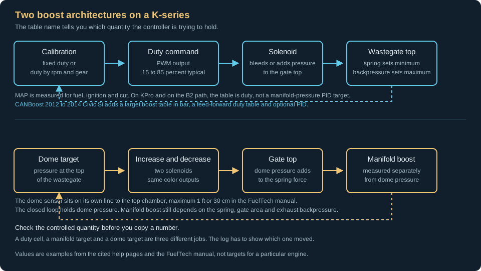
Swipe or use the arrow keys to read every label.
More details
The spring and the installed gate system establish the minimum boost curve. A spring rating or bench crack pressure is not an exact manifold-boost prediction. Exhaust pressure, gate placement and pressure-source routing change the result.
A controller can raise boost by pressurizing the top chamber or reducing the opening pressure below the diaphragm. It cannot cure insufficient exhaust bypass flow. Rising boost with the gate fully open calls for a gate-flow or placement fix.
| Route | Quantity in the table | Feedback | What you edit |
|---|---|---|---|
| KPro / KManager | Duty to the purge output; fixed or Boost vs Gear through a Pressure vs Duty lookup | Manifold MAP is measured, but the duty path is a lookup, not a PID | Target pressure, duty and measured pressure/duty pairs |
| FlashPro B2 / B16 | Duty; fixed or duty by rpm and gear | Documented tables are duty; target boost is the CANBoost path | Duty cells |
| FlashPro CANBoost, 2012–2014 Civic Si | Target boost in bar plus a feed-forward duty table | PID can trim duty toward the target | Target boost and feed-forward duty |
| FuelTech generic duty output | PWM duty by rpm, time, speed, MAP, gear and rpm, or gear elapsed time | No dome feedback | Duty table |
| FuelTech BoostController | Dome pressure target at the top of the wastegate | Dome pressure sensor; dual 2-way or single 3-way valve mode | Dome target, gain and mode |
More details
For a made-up lookup example, suppose fixed 30% duty produces 8 psi and 40% produces 12 psi under matched conditions. A 10 psi request interpolates to 35% duty between those points. If colder air later produces 11 psi at that command, KPro does not automatically learn a new pressure/duty pair.
Recheck the characterization and available compensation. These figures illustrate interpolation, not starting duties.
- KPro's gear-based path uses Boost vs Gear to choose a target pressure, then Pressure vs Duty Cycle to choose duty. The second table is a measured characterization. It is not a feedback loop that holds manifold pressure.
- FlashPro's B2 and B16 paths name duty. Fixed duty gives a fairly flat curve. Duty cycle by Rpm & Gear gives a table per gear. Neither table is a manifold-pressure target.
- CANBoost is the exception. It has a target boost table in bar and a duty feed-forward table. PID can add or subtract duty until MAP reaches the target. That is a manifold-pressure loop, and it is only on the CANBoost path described in the 2012–2014 Civic Si help.
4. The log that proves which loop you are in
One log can tell you which quantity the controller is holding. Log MAP, the command and dome pressure where fitted. Add rpm, gear or speed, throttle, lambda and target lambda. Add injector pulse or duty, fuel pressure where fitted, intake and coolant temperature, and knock or timing retard.
| Quantity | KManager | FlashPro | FTManager | What it settles |
|---|---|---|---|---|
| Manifold pressure | map in bar | MAP where supported | MAP input | Absolute pressure, sensor range and saturation |
| Command | Duty table or boostduty if exported | Boost duty or target boost where exposed | Generic duty or dome target and actual | Which quantity the controller is holding |
| Dome pressure | Not applicable | Not applicable | Wastegate pressure input | Dome pressure versus MAP |
| Mixture | lambda, targetlambda | Lambda and target where supported | O2 target and actual | Fuel delivery against target |
| Injector | injector in ms | Pulse or duty where supported | Injection pulse or duty | Headroom and event count |
| Fuel pressure | Not in the documented CSV list | Only if an input is configured | Configured pressure input | Differential pressure and supply |
| Gear and speed | speed if exported; gear if present | Speed and gear where supported | Gear and speed | Boost by gear and VSS scaling |
| Knock and timing | ignition; knock channels where present | Knock and timing where supported | Timing; external knock monitoring if installed | Delivered spark and available knock evidence |
The KManager documented CSV list includes time, map, air and coolant temperature, lambda and target lambda. It also includes injector, ignition, cam angle and target cam angle, rpm and throttle. Load and short and long term trim are listed too. It also lists knockcount. It does not promise boost duty, fuel pressure or every knock signal, so inspect the actual export header.
- FlashPro's sensor list is ECU specific. The CANBoost path can log target boost and duty where the calibration exposes them. The B2 path logs duty if the channel is present. FTManager logs are native
.ftmlwith CSV export, and configured inputs decide what exists. MAP and dome pressure are separate inputs. - A good trace repeats. The command is steady, and MAP follows with a known lag. Dome pressure holds where it is fitted, and lambda follows target while injector pulse stays stable. A bad trace changes the story: MAP climbs while dome is flat, target is met while duty climbs, or MAP rises at 0% command.
- The channel list is on the Honda datalog page.
5. Hondata: what the KPro and FlashPro tables command
KManager runs boost from the purge output. Configuration selects normally open or normally closed, minimum and maximum duty, activation pressure and frequency. Fixed duty is one command. Gear-based uses Boost vs Gear and Pressure vs Duty Cycle.
Fill the pressure/duty table from measured pairs at fixed duty, then let the lookup choose duty. Do not type a curve from another car.
More details
KPro4 can run true target lambda at high load. In Closed Loop Advanced, enable the target lambda tables. Set the target table rich enough for the boost you will run, then disable the fixed 0.85 wide-open compensation.
That fixed 0.85 value is the rich wide-open adder; the factory fuel tables are stoichiometric, and leaning the target raises exhaust gas temperature. Raise Maximum MAP for closed loop and set Closed Loop Max TPS to 100.
The old rule that a KPro must be open loop above 110 kPa describes an older strategy, not a KPro4 hardware limit. The wideband still has to be valid and the authority bounded.
Create Forced Induction Tables initializes the boost columns. It copies or extrapolates fuel and can apply a retard per psi. It does not measure VE, fuel pressure loss or the knock limit. Check every active cam copy and every new axis before a load.
On a 2006–2011 Civic Si the output is B2. On a 2007–2008 TSX it is B16 where the calibration exposes boost. Both are high-side current sources. One solenoid wire goes to the output through a 10 A fuse, and the other goes to ground.
The solenoid should draw less than 1 A at 14 V. No relay, no added suppression diode.
On that path, frequency is 10–100 Hz, and most solenoids work in 10–60 Hz. The effective duty range for most solenoids is 15–85%, and the FlashPro help recommends staying inside it. Those are hardware starting points, not a target. The 2012–2014 Civic Si CANBoost path is different.
It adds target boost in bar by gear and rpm, a duty feed-forward table and optional PID. It also adds max boost by speed, throttle compensation and intake air compensation.
Boost control arrived in FlashProManager 4.5.0 on 19 June 2025 for the 2012–2015 Si. Version 4.5.2 already mentions a target-boost log channel, and 4.5.3 fixes target-table gear indexing.
The 4.6.5 entry says it added boost target and duty, but that does not date the first target table. Inspect the actual calibration rather than using 4.6.5 as a minimum table version.
The FlashPro boost help calls B2 a duty-controlled current source and says it needs different wiring from the s300 or KPro. One wire to B2 through a 10 A fuse, the other to ground, is the documented circuit.
Do not power the solenoid from a switched 12 V source and let the ECU ground the other wire. That is a different output type. Wire the exact car from its install page.
6. Commission a Hondata boost output
- Record the hardware and the references. MAP part and transfer, wastegate spring crack pressure, gate plumbing, injector part and data, pump, fuel pressure, wideband and ECU or software version. Stop if key-on MAP does not read local barometric pressure, or if the sensor part does not match the calibration.
- Set the cut before the command. Hot and cold boost cut, below the sensor ceiling with margin, plus lean protection. Stop if the intended boost is above the sensor range or above the cut you can actually set.
- Measure the mechanical baseline. For a conventional dual-port gate, connect the lower chamber directly to the pressure reference and vent the top. Isolate the controller pressure feed first. Log the resulting boost curve; it need not equal the spring label. Stop for uncontrolled rise, a missing pressure reference or an actuator that does not open on a regulated-air check.
- Configure the output and the solenoid. KPro purge, FlashPro B2 or B16, or CANBoost. Set normally open or closed, minimum and maximum duty, frequency and activation pressure. Confirm the safe state. For B2/B16, stop if current reaches 1 A at 14 V, or the circuit has a relay or an added diode. Other drivers need their own current limits.
- Characterize at a fixed command. On KPro, fill Pressure vs Duty from measured pairs. On B2/B16, fill the rpm and gear duty table. On CANBoost, turn PID off first and set target plus feed-forward. Investigate an unexplained change under matched conditions. Stop for a lean departure from target, fuel-pressure loss or new knock.
- Add gear targets only after the gear is right. Check the speed signal and the displayed gear. Then set Boost vs Gear or the CANBoost target. Stop if the displayed gear does not match the selected gear, or if a boost-by-gear row moves the wrong gear.
- Add compensations last. Use the compensations available on the selected route; throttle compensation here belongs to CANBoost. For quick spool, the help recommends 1 psi activation and pressures 1 or 2 psi below target. Stop if the overshoot crosses the cut or the boost does not repeat hot and cold.
- Check commanded minimum and power loss separately. With the engine off, use regulated air and a pressure gauge on the control assembly. Verify displayed 0% gives the intended minimum-boost routing, then check the valve paths with power removed. Normally open configurations can feed the top chamber on power loss. A bench test verifies routing and actuator motion; it does not measure manifold boost. Keep the top chamber isolated from pressure during any engine-running electrical checks.
7. FuelTech: three functions that get confused
FuelTech separates three functions that are easy to call the same thing. A generic duty cycle output sends PWM. A boost activated output is an on/off switch based on MAP. Wastegate boost pressure control is the BoostController, and it regulates pressure at the top of the wastegate.
| Function | What it does | What it does not do |
|---|---|---|
| Generic duty cycle output | PWM by rpm, time, speed, MAP, gear and rpm, or gear elapsed time | It does not read dome pressure |
| Boost activated output | Switches an output on or off when MAP crosses a setting, with minimum rpm and throttle conditions | It does not regulate pressure |
| Wastegate boost pressure control | Closed-loop dome pressure with a dedicated sensor and dual 2-way or single 3-way valve mode | It does not target manifold MAP |
The generic duty output can run a boost solenoid the way a Hondata duty table does. The manual recommends 20 Hz for most PWM 3-way valves. The output can be scheduled by rpm, time, speed, MAP, gear and rpm, or gear elapsed time.
It is open loop unless you add a feedback device elsewhere.
More details
The boost activated output is a switch. It has three activation modes: always active, active only on 2-step, and not active only on 2-step. It also has minimum rpm and throttle thresholds. It is useful for a secondary device, not a boost curve.
The BoostController is the dome-pressure loop. The sensor goes on an exclusive line to the top chamber, maximum 1 ft or 30 cm. For dual-valve mode, the manual recommends two yellow outputs or two blue outputs, not a mix.
Modes include time after 2-step, gear and engine rpm, gear elapsed time, single target, engine rpm and launch targets. Max MAP and max MAP on 2-step are safety limits. The manual says those limits do not regulate to a target and the pressure will bounce around the limit.
They do not cut fuel or spark.
A dome target is not a manifold target. The gate sees spring force plus dome pressure on the closing side, and boost plus exhaust backpressure on the opening side. Learn the transfer on your gate by logging dome and MAP together.
A 10 psi dome target can make more or less than 10 psi manifold boost. The pressure source can be intake or a regulated CO2 bottle. The bottle needs a regulator and two gauges.
Source pressure changes the available control authority and response, so characterize the dome-to-MAP relationship with the installed source. The manual marks dual 2-way valve mode as CO2 compatible and single 3-way valve mode as not CO2 compatible. A regulated bottle on the single 3-way mode is the combination the manual excludes.
8. Commission a FuelTech boost setup
- Draw the pneumatic system. Pressure source, gate bottom, gate top, fill path, vent path, sensor and the failure position of each valve. Decide between generic duty and the BoostController. Stop if you cannot name the chamber and the failure position for every valve.
- Allocate outputs and sensors. In dual-valve mode, use same-color outputs for the increase and decrease solenoids. Verify driver current and suppression from the FuelTech documentation. Keep MAP and dome pressure on separate inputs. Stop if dual-valve outputs mix colors or the dome sensor shares a line.
- Calibrate both pressure channels. Key-on reference, then a regulated known pressure on each sensor. Stop if dome reads manifold, if either channel does not hold a known pressure, or if the sensor is not the type configured in FTManager.
- Establish spring-only boost. Verify that the top chamber vents and the lower chamber has the intended pressure reference before the baseline run. Record the mechanical boost curve rather than expecting an exact match to the spring rating. Stop for uncontrolled rise or a failed reference line.
- Characterize dome to MAP at one target. Use single-target mode and log both pressures. Stop if dome is flat and MAP climbs. Fix the gate, the plumbing or the backpressure before you touch gain.
- Choose the mode and verify the timer. Time after 2-step, gear and rpm, gear elapsed time, single target or rpm. The time-based test works with the engine off. With the engine running, a valid launch requires 2-step plus TPS above 50% or reaching the 2-step limiter. Verify the launch state and timer reset before interpreting the curve. Stop if the intended mode never starts.
- Set gain and the safety limits. Raise gain if dome is slow, lower it if it overshoots. Set max MAP and max MAP on 2-step as backstops. The limits do not cut fuel or spark; the pressure bounces around the setting. Stop for oscillating actual dome pressure or MAP exceeding the intended limit. Verify limit operation with suitable signal simulation; do not deliberately overboost the engine.
- Recheck fuel and spark at the new boost. Lambda against target, injector pulse, fuel pressure and knock. Stop for a lean departure from target, falling fuel differential pressure or knock. An absent knock channel does not establish knock-free operation.
9. Fuel and spark under load
Boost does not create a fuel target. The target lambda table and the fuel model do. Read the active fuel model, the injector data and the differential pressure before changing a cell. On FlashPro the model can be AFM, MAP or hybrid. On KPro the raw values are not VE percent everywhere.
More details
- At boost, the injector sees rail pressure minus manifold pressure. If rail gauge stays fixed, differential pressure falls as boost rises. The fuel table can hide that until injector duty or pump duty runs out. Log fuel pressure and injector pulse together. Treat a lean trend with falling differential pressure as a supply problem before you add fuel to the table.
- One injection event per 720 degrees gives a cycle time of
120000 / rpmms. At 8000 rpm that is 15 ms; 12 ms is 80%. KManager suggests planning an injector or fuel-system upgrade at 80–85% duty. Confirm the event count and whether the logged pulse includes latency before you use the equation on a staged or paired setup. - In the rail example, differential pressure falls from 50 to 35 psi. Maintaining fuel mass needs
1 / 0.837 = 1.195times the pulse. A 12 ms pulse becomes 14.34 ms, or 95.6% of the 15 ms cycle at 8000 rpm. That idealized calculation ignores latency and flow nonlinearity. It shows why closed-loop correction can consume the remaining injector capacity while lambda still looks right. - No retard-per-psi value is printed here. A value can seed a table, and Create Forced Induction Tables can apply one, but it does not find the knock limit or MBT. Read the delivered spark, the knock count and the torque response. A log without a torque measurement cannot establish MBT.
- Turning knock sensitivity down because the engine is noisy hides the count. It does not prove the count is false. A single count is not a damage allowance, and a repeated count at full boost is a reason to stop. The ignition and knock page covers the count, the relative retard limit and the delivered spark.
- There is no universal low VTC angle for a turbo K. Backpressure and cam geometry decide. Measure torque and phase, and establish mechanical clearance before a target. E85 does not change clearance and is not an automatic timing or boost adder.
- Fuel tables, ignition and cam angle are separate jobs on this site: fuel tables, ignition and knock, and VTC and VTEC. E85 and flex fuel are on their own page.
10. Protection and the failure you can test
KManager boost cut has a cold limit and a hot limit. It cuts fuel and restores when the throttle is released or engine speed falls below 2,000 rpm. With a stock MAP sensor the maximum cut is 10.5 psi.
Set it below the sensor ceiling with margin, and set it before the first boost run.
- Lean protection uses Maximum Lambda, Engine Load and Trigger Time. It needs a working front wideband. It cuts and restores at throttle release or below 2,000 rpm. The help warns that lean protection is disabled after launch when the launch-control rev limiter is active. Verify this interaction in the installed version. These are conditions to verify on the car, not numbers to copy from a table.
- FuelTech's max MAP and max MAP on 2-step are safety limits. The manual says they do not regulate to a target and the pressure will bounce around the limit. They do not cut fuel or spark. Use them as a backstop, not as the boost curve.
- Configure FuelTech engine protection separately from the BoostController pressure limits. Overboost and fuel differential-pressure alerts can use a configured safe mode, including an rpm limit or engine shutoff. Verify the selected response and required sensor inputs in the actual file.
- A cut is a backstop, not a control. A normally open solenoid that loses power or wiring can go to maximum boost. A normally closed valve can return the system to its mechanical baseline when the plumbing vents the top and preserves the lower reference. Know which one you have, and test the failure state with the gate safe.
- With the engine off, test displayed minimum and power loss separately using regulated air. Confirm the pressure paths and gate motion. For engine-running electrical checks, isolate pressure from the top chamber first. Test protection inputs through suitable signal simulation, keeping the wiring and sensor transfer valid. A valve-routing test does not prove that the ECU's boost or lean cut works.
11. Numbers used on this page
| Number | What it belongs to | What it does not mean |
|---|---|---|
| 1.8 bar absolute / 11.4 psi boost | Stock K MAP sensor ceiling in KManager | Not a safe boost limit |
| 10.5 psi | Maximum stock-sensor boost cut in KManager | Not a target; a replacement sensor requires its matching calibration |
| 862.5 mbar/V, −431.25 mbar | 3.5-bar transfer example in KManager | Not every 3.5 or 4 bar sensor |
| 43.3 psi gauge | 4-bar absolute sensor at full scale, near sea level | Not 58 psi gauge; the fuel, ignition and cam axes are mapped only to 28 lbs, and it leaves no cut margin |
| 16.3% flow loss | 50 psi rail, 15 psi boost, no 1:1 reference | Not a K rail specification |
| 15–85% duty | Effective range for most solenoids, FlashPro help | Not a target window, and not a promise |
| Less than 1 A at 14 V; 10 A fuse | B2 / B16 current-source output | The fuse rating is not the solenoid current |
| 15 ms at 8000 rpm; 12 ms is 80% | One injection event per 720 degrees | Not valid until the event count is confirmed |
| 4.5.0 on 19 June 2025; target-table references in 4.5.2/4.5.3 | 2012–2015 Civic Si release history; does not establish when target tables first appeared | Not a requirement for a 2006–2011 B2 car |
No universal boost ceiling, no retard-per-psi value, no dome-to-manifold ratio, no injector horsepower rating and no target lambda column. Those come from the sensor, the gate, the fuel and the log. A copied number does not describe your engine.
Questions
Why can't I lower boost below the wastegate spring?
The mechanical gate system establishes the minimum boost curve. Confirm a direct lower-chamber reference and a vented top chamber first. If that baseline is stable but too high, a softer spring may be needed.
If boost keeps climbing with the gate open, correct gate flow or placement before changing the spring or duty table.
Why does boost rise with the solenoid at 0% duty?
First check what 0% means. A normally open solenoid gives maximum boost at 0% electrical duty. KManager and FlashPro invert duty when configured normally open, so displayed 0% means minimum boost. If the display and the valve disagree, the command is inverted.
If they agree, check for creep, a disconnected hose, a stuck valve or a gate that cannot bypass enough exhaust. A boost table does not fix a mechanical gate problem.
Is a 4-bar MAP sensor enough for 43 psi?
A 4-bar absolute sensor reaches about 43.3 psi gauge at full scale near sea level. That is the ceiling, not a working target. A 40 psi target leaves 3.3 psi to nominal full scale at that ambient pressure. Allow room for overshoot, the cut threshold and sensor tolerance.
Use a higher-range sensor or a lower target if that margin is insufficient. Check the actual transfer curve at both endpoints. The label on the sensor is not the calibration.
What does a 10 psi dome target mean on a FuelTech?
It means the controller is trying to hold 10 psi at the top of the wastegate. It does not mean 10 psi in the manifold. Manifold boost depends on the spring, the gate area, the dome pressure and exhaust backpressure. Log dome and MAP together and learn the transfer on your gate.
The numbers are not interchangeable; a stable dome can coexist with rising MAP.
Can I copy a KPro duty table into a FuelTech?
No. The numbers describe different quantities and different hardware. A KPro Boost vs Gear cell requests pressure; Pressure vs Duty Cycle converts that request to duty. A FuelTech BoostController cell is dome pressure. A FuelTech generic duty cell is PWM, but the output and the plumbing still differ.
Copying a table loses the meaning of the number. Build the FuelTech table from its own dome and MAP log.
Can I use one retard-per-psi number?
Only as an initializer, and only with the understanding that it is a guess. A retard-per-psi value can seed a table, but it does not find the knock limit or MBT on your engine. Compression, fuel, intake temperature, backpressure and cam angle all move the limit.
Read the delivered spark and the knock count, and treat a repeated count at full boost as a stop.
Will the boost cut limit a failed solenoid?
It can limit the event only if the cut is set below the sensor ceiling and the sensor can see the pressure. A normally open solenoid that loses power or wiring can go to maximum boost, and a cut set at the sensor's top may never trigger.
Test the failure state with the gate safe, and keep the cut as a backstop rather than the plan.
Why are the boost tables missing on a 2012–2014 Civic Si?
That car uses the CANBoost hardware route, not the B2 output. Boost control arrived in FlashProManager 4.5.0; target-table references already appear in 4.5.2 and 4.5.3. The 4.6.5 changelog is not proof that earlier files lack targets. Check the kit, firmware, calibration and software together.
Updating software alone does not add the controller, and the earlier B2 wiring does not apply. Confirm the exact application and the installed kit before you chase a missing table.
Is B2 wired like a normal 12 V solenoid?
No. B2 is a duty-controlled current source, high side. One solenoid wire goes to B2 through a 10 A fuse, and the other goes to ground. The solenoid should draw less than 1 A at 14 V. There is no relay and no added suppression diode in the documented circuit.
A switched 12 V feed with the ECU grounding the other wire is a different output type. Wire the exact car from its install page.
Does 15% minimum duty mean boost is spring pressure divided by 0.15?
No. Duty is the fraction of the electrical cycle assigned to the valve. Its pressure response depends on valve flow, frequency and plumbing. The 15–85% range describes useful valve operation, not a boost multiplier. Measure the mechanical baseline and then record pressure at fixed commands.
Why is my four-port MAC boost control jumpy?
A four-port installation changes pressure on both sides of the diaphragm. A three-port duty curve and hose diagram do not carry over. On the Hondata four-port external-gate diagram, A feeds the top, B feeds the bottom, IN takes the boost reference and EX vents.
Verify those labels against your exact MAC valve before applying that routing. Check the exact valve's port map, output polarity, frequency and hose restrictions, then repeat fixed-duty measurements with quick spool disabled. Reduce the command spacing where small duty changes produce large pressure changes.
KPro's documented pressure lookup does not provide manifold PID correction; replacing the valve still requires a new characterization.
Boost falls off up top. Is that the tune or the turbo?
Compare MAP with duty, throttle and dome pressure where fitted. Falling duty or throttle points toward the command or a limiter. Dome missing its target points toward the pressure supply, valves, leaks or control settings. Stable dome with falling MAP needs a gate, reference-line, exhaust-pressure and turbo-flow check.
Increasing exhaust pressure can open the gate earlier; correcting the wastegate pressure-source location can resolve that form of falloff. More duty will not repair a leak or create turbo flow capacity.
I fitted a 4-bar MAP sensor. Why is the reading wrong?
In KManager, select the matching curve under Parameters, MAP, or enter the sensor's measured scalar and offset. Then check an independent pressure reference and a regulated second point. Changing the sensor selection does not extend the fuel, ignition or cam axes.
A flat reading with pressure changing needs a connector, supply, ground and signal check before further tuning. Correcting the scale also does not repair unrelated injector or wideband errors.
Is a turbo basemap safe to drive in boost?
A basemap does not verify injector data, fuel delivery, MAP scaling or the active cam tables on your engine. Keep it out of boost until those checks are complete. When fuel or spark changes seem inconsistent, hold a mechanically permitted cam angle and compare commanded with actual phase.
Tune the active cam and lobe tables before building the final cam schedule. Editing different cam blends on successive runs can make a fuel-table error look like a boost-control fault.
Tune Report is free. Send the calibration, the native log, the CSV export, the ECU or device identity, the fuel and the hardware list. Honda Full Custom is open at $199 during the launch special ($249 regular).
Every file is compared against our 3 million+ tune values, with a final check-off by our lead tuner.
← Previous: Idle and injectors
Tune Report is free if you want this file checked: open the Honda & Acura Tune Report.
A written review of your tune file and one log from your car.
Start a Honda & Acura Tune Report